The IP Endpoint Company VoIP Paging Gateway Operations Guide Part #010846 Document Part #930098E for Firmware Version 3.
VoIP Paging Gateway 930098E SiP Compliant 010846 COPYRIGHT NOTICE: © 2011, CyberData Corporation, ALL RIGHTS RESERVED. This manual and related materials are the copyrighted property of CyberData Corporation. No part of this manual or related materials may be reproduced or transmitted, in any form or by any means (except for internal use by licensed customers), without prior express written permission of CyberData Corporation.
Revision Information Revision 930098E, which was released on August 5, 2011 and corresponds to firmware version 3.00, has the following changes: • Updates Figure 2-6, "Test/Reset Switch".
Important Safety Instructions 1. Read these instructions. 2. Keep these instructions. 3. Heed all warnings. 4. Follow all instructions. 5. Do not use this apparatus near water. 6. Clean only with dry cloth. 7. Do not block any ventilation openings. Install in accordance with the manufacturer’s instructions. 8. Do not install near any heat sources such as radiators, heat registers, stoves, or other apparatus (including amplifiers) that produce heat. 9.
Pictorial Alert Icons General Alert This pictoral alert indicates a potentially hazardous situation. This alert will be followed by a hazard level heading and more specific information about the hazard. GENERAL ALERT Ground This pictoral alert indicates the Earth grounding connection point. Hazard Levels Danger: Indicates an imminently hazardous situation which, if not avoided, will result in death or serious injury. This is limited to the most extreme situations.
Contents Chapter 1 Product Overview 7 1.1 Product Features .....................................................................................................................................7 1.2 Supported Protocols ..............................................................................................................................8 1.3 Product Specifications ...........................................................................................................................
1 Product Overview The VoIP Paging Gateway enables access to existing paging speakers through a VoIP phone system. This interface uses a standard paging amplifier, and supports paging to multiple zones from a VoIP phone. 1.
1.2 Supported Protocols ● Asterisk™ SIP server Offers Open Source benefits with the rich and flexible feature set of a large, proprietary PBX system. ● HTTP Web-based configuration Provides an intuitive GUI for easy system configuration and verification of gateways operations. ● DHCP Client Dynamically assigns IP addresses in addition to the option to use static addressing. ● TFTP Client Facilitates Web-based firmware upgrades of the latest speaker capabilities.
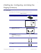
2 Setting Up, Configuring, and Using the Paging Gateway 2.1 Parts List The packaging for the VoIP Paging Gateway includes the parts shown in Table 2-1. Table 2-1.
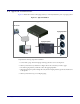
2.2 Typical Installation Figure 2-1 illustrates how the VoIP Paging Gateway is normally installed as part of a paging system. Figure 2-1. Typical Installation PoE VoIP Paging Gateway VoIP Phone Paging Speakers FXO Paging Amplifier FXS IP PBX Complete the following steps after installation: 1. Call to make a page. The VoIP Paging Gateway generates a tone over the phone. 2. When you hear the tone, enter the two-digit code for the zone that you want to page.
2.3 Setting up the VoIP Paging Gateway Before you set up the VoIP Paging Gateway, be sure that you have received all the parts described in Section 2.1, "Parts List". To set up the VoIP Paging Gateway, see the following sections: ● Section 2.3.1, "Connect to the Power Source" ● Section 2.3.2, "Connect to the Network" ● Section 2.3.3, "Confirm that the VoIP Paging Gateway is Working Properly" ● Section 2.3.3.1, "Confirm Power on, Network Connectivity, and Connection Speed" ● Section 2.3.3.
2.3.2 Connect to the Network Plug one end of a standard Ethernet cable into the Paging Gateway Ethernet port. Plug the other end into your network. Figure 2-3.
2.3.3 Confirm that the VoIP Paging Gateway is Working Properly The indicator lights on the front of the VoIP Paging Gateway verify the unit’s operations. Figure 2-4. Paging Gateway Indicator Lights Link Test/Reset switch On when network connection is established Orange when baud rate = 100Mbps Yellow when baud rate = 10Mbps Act. Status Paging Blinks to indicate network activity Blinks when unit is up and running Blinks when unit is paging 2.3.3.
2.3.4 Connect to a Paging Device You can broadcast test messages via two different paging devices: ● A paging amplifier, which you use for normal paging operations, broadcasts the test message to the speakers in a specified paging zone. To do so, you need to first see Section 2.3.4.1, "Connect the VoIP Paging Gateway to a Paging Amplifier". ● Via a Plain Old Telephone (POT), which broadcasts the test message to you over the phone. See Section 2.3.4.2, "Connect the VoIP Paging Gateway to a Telephone". 2.
2.3.5 Broadcast a test message to all paging zones The Test/Reset switch is located on the back of the VoIP Paging Gateway (see Figure 2-6). The Test/ Reset switch enables testing to all paging zones and lets you restore the VoIP Paging Gateway to its factory default settings. Figure 2-6. Test/Reset Switch Test/Reset switch Once the VoIP Paging Gateway is running and connected to a paging device, use the Test/Reset switch to broadcast a test message to all of the zones in the paging system.
2.3.6 Restore the Factory Default Settings as Required The VoIP Paging Gateway is delivered with factory set default values for the following parameters. Use the Test/Reset switch on the back of the unit to restore these parameters to the factory default settings. Note When you perform this procedure, the factory default settings are restored for all the following parameters. Parameter Factory Default Setting IP Addressing static IP Address 192.168.3.
2.4 Configuring the VoIP Paging Gateway Complete the following sections to configure the VoIP Paging Gateway online: ● Section 2.4.1, "Gather the Required Configuration Information" ● Section 2.4.2, "Log in to the Configuration GUI" ● Section 2.4.3, "Configure the Network Parameters" ● Section 2.4.4, "Change the Default Username and Password" ● Section 2.4.6, "Configure the SiP Parameters" 2.4.
2.4.2 Log in to the Configuration GUI To log in: 1. For the initial configuration of the VoIP Paging Gateway, open your browser and enter the following address: http://192.168.3.10 Note To work with the VoIP Paging Gateway configuration after the initial configuration, log in using the IP address you assign to the device. Section 2.4.3, "Configure the Network Parameters" provides instructions for entering the IP address. 2.
3. On the Home Page, review the setup details and navigation buttons described in Table 2-1. Table 2-1. Home Page Overview Web Page Item Description Device Name Shows the device name. Serial # Device serial number. Ethernet Address Device ethernet address. IP Addressing Shows the current IP addressing setting (DHCP or static). IP Address Shows the current IP address. Subnet Mask Shows the current subnet mask address. Default Gateway Shows the current default gateway address.
2.4.3 Configure the Network Parameters Configuring the network parameters enables your network to recognize the VoIP Paging Gateway and communicate with it. Click Network Setup on the Home page to open the Network Configuration page. Figure 2-8.
4. On the Network Setup page, enter values for the parameters indicated in Table 2-2. Table 2-2. Network Setup Parameters Web Page Item Description IP Addressing* Select either DHCP IP Addressing or Static IP Addressing by marking the appropriate radio button. If you select Static, configure the remaining parameters indicated in Table 2-2. If you select DHCP, go to Step 3. IP Address* Enter the Static IP address. Subnet Mask Enter the Subnet Mask address.
2.4.4 Change the Default Username and Password On the Home page, click Gateway Setup to open the Gateway Configuration page. After changing the Username and Password settings on this page, you will be required to log in using these new parameters. Note You can also run an audio test from this page. See Section 2.4.5, "Broadcast a Test Message to a Specific Paging Zone" for more information. Figure 2-9.
4. On the Gateway Setup page, enter values for the parameters indicated in Table 2-3. Table 2-3. Gateway Setup Parameters Web Page Item Description Device Name Enter the name of the device.
2.4.5 Broadcast a Test Message to a Specific Paging Zone Once the VoIP Paging Gateway is set up and configured, you can broadcast test messages to different paging zones that you specify. On the Home page, click Gateway Setup to open the Gateway Configuration page. Note You can broadcast a test message to all paging zones by using the Test/Reset switch on the back of the VoIP Paging Gateway. See Section 2.3.5, "Broadcast a test message to all paging zones" for instructions. Figure 2-10.
2.4.6 Configure the SiP Parameters The SIP parameters enable the VoIP Paging Gateway to contact and register with the SIP server. On the Home page, click SIP Setup to open the SIP Configuration page. Figure 2-11.
3. On the SIP Setup page, enter values for the parameters indicated in Table 2-4. Table 2-4. SIP Setup Parameters Web Page Item Description SIP Server* Enter the SIP server represented as either a numeric IP address in dotted decimal notation or the fully qualified host name (FQHN) up to 64 characters. Outbound Proxy Enter the Outbound Proxy as either a numeric IP address in dotted decimal notation or the fully qualified host name (FQHN) up to 64 characters.
Complete the following steps: 1. Enter the IP address of the SIP Server. 2. Enter the port numbers used for SIP signaling: a. Remote SIP Port b. Local SIP Port 3. Enter the SIP registration parameters: a. SIP User ID b. Authenticate ID c. Authenticate Password 4. For SIP Registration, designate whether you want the IP Gateway to register with your SIP server. 5. At Unregister on Reboot: a. Select Yes to automatically unregister the VoIP Paging Gateway when you reboot it. Section 2.
2.5 Upgrading the Firmware The firmware on the board consists of two files: a Kernel and an Application, that can be loaded separately. Uploading the firmware files requires a host machine running a TFTP server. If you need to set up this server, see Appendix A, “Setting up a TFTP server” for instructions. Figure 2-12. Firmware Upgrade Page To upload a firmware file, log in as instructed in Section 2.4.2, "Log in to the Configuration GUI". Table 2-5 shows the web page items on the Firmware Upgrade page.
Table 2-5. Firmware Upgrade Parameters (continued) Web Page Item Description Click on this button to automatically upload the selected firmware and reboot the system. Link to the Network Setup web page. Link to the Gateway Setup web page. Link to the SIP Setup web page. Link to the Home page. Click on this button to reboot the system. To upgrade the firmware for the Paging Gateway, complete the following steps: 1. On the Home page, click Upgrade Firmware to open the Firmware Upgrade page. 2.
2.6 Rebooting the VoIP Paging Gateway To reboot the system, complete the following steps: 1. Log in as instructed in Section 2.4.2, "Log in to the Configuration GUI". 2. On the Home page, click Upgrade Firmware to open the Firmware Upgrade page. See Figure 2-13. Figure 2-13. .Firmware Upgrade Page 3. Go to the Reboot section on the right side of the page. 4. Select Partition 1 or Partition 2 for the Kernel and the Application. 5. Click Reboot.
Appendix A: Setting Up a TFTP Server A.1 Set up a TFTP Server Autoprovisioning requires a TFTP server for hosting the configuration file. A.1.1 In a LINUX Environment To set up a TFTP server on LINUX: 1. Create a directory dedicated to the TFTP server, and move the files to be uploaded to that directory. 2. Run the following command where /tftpboot/ is the path to the directory you created in Step 1: the directory that contains the files to be uploaded. For example: in.
Appendix B: Troubleshooting/Technical Support B.1 Frequently Asked Questions (FAQ) A list of frequently asked questions (FAQs) are available on the VoIP Paging Gateway product page at: http://www.cyberdata.net/products/voip/legacyanalog/paginggateway/faqs.html Select the support page for your product to see a list of frequently asked questions for the CyberData product: B.2 Documentation The documentation for this product is released in an English language version only.
B.3 Contact Information Contact CyberData Corporation 3 Justin Court Monterey, CA 93940 USA www.CyberData.net Phone: 800-CYBERDATA (800-292-3732) Fax: 831-373-4193 Sales Sales 831-373-2601 Extension 334 Technical Support Phone: 831-373-2601 Extension 333 Web: http://www.cyberdata.net/support/contactsupportvoip.html Returned Materials To return the product, contact the CyberData Returned Materials Authorization (RMA) department Authorization at: Phone: 831-373-2601, Extension 136 Email: RMA@CyberData.
B.4.1 Warranty & RMA Returns within the United States If service is required, you must contact CyberData Technical Support prior to returning any products to CyberData. Our Technical Support staff will determine if your product should be returned to us for further inspection. If Technical Support determines that your product needs to be returned to CyberData, an RMA number will be issued to you at this point. Your issued RMA number must be printed on the outside of the shipping box.
Index Symbols contact information for CyberData 33 current settings, reviewing 19 +48V DC power supply 11 D Numerics default gateway 16 IP address 16 subnet mask 16 username and password 16 default gateway 16, 21 default gateway for static addressing 21 default password for configuration GUI 18 default settings, restoring 16 default username and password for configuration GUI 18 DHCP addressing 17, 21 DHCP Client 8 DHCP IP addressing 21 dimensions 8 DNS server 21 DTMF detection 8 dual speeds 7, 13
green light, blinking 15, 24 green link light 13 green paging light 13 GUI username and password 22 network, connecting to 12 O orange link light 13 outbound proxy 26 H hazard levels 5 http web-based configuration 8 P paging amplifier connecting to 14 in typical installation 10 paging gateway configuration 17 paging light 13, 15, 24 paging speakers in typical installation 10 paging zones 15, 24 part number 8 parts list 9 password configuration GUI 17, 22 for SIP server login 26 restoring the default
ring out 23 RMA returned materials authorization 33 RMA status 33 RTP Audio Version 2 8 restoring the default 16 username for configuration GUI 17, 22 V S verifying network activity 13 VoIP phone in typical installation 10 safety instructions 4 server SIP 19 TFTP 28, 31 server address, SIP 26 SIP configuration SIP Server 26 SIP configuration page 25 SIP registration 26 SIP server 26 SIP server configuration 19 SIP server parameters, configuring 17 SIP setup button 19, 25 Spare in the Air Policy 34 s