VoIP Intercom Operations Guide Part #010935B Document Part #930242F for Firmware Version 3.3.
PoE VoIP Intercom Operations Guide 930242F Part # 010935B COPYRIGHT NOTICE: © 2009, CyberData Corporation, ALL RIGHTS RESERVED. This manual and related materials are the copyrighted property of CyberData Corporation. No part of this manual or related materials may be reproduced or transmitted, in any form or by any means (except for internal use by licensed customers), without prior express written permission of CyberData Corporation.
Important Safety Instructions 1. Read these instructions. 2. Keep these instructions. 3. Heed all warnings. 4. Follow all instructions. 5. Do not use this apparatus near water. 6. Clean only with dry cloth. 7. Do not block any ventilation openings. Install in accordance with the manufacturer’s instructions. 8. Do not install near any heat sources such as radiators, heat registers, stoves, or other apparatus (including amplifiers) that produce heat. 9.
Pictorial Alert Icons GENERAL ALERT General Alert This pictoral alert indicates a potentially hazardous situation. This alert will be followed by a hazard level heading and more specific information about the hazard. Ground This pictoral alert indicates the Earth grounding connection point. Hazard Levels Danger: Indicates an imminently hazardous situation which, if not avoided, will result in death or serious injury. This is limited to the most extreme situations.
Revision History Revision Date Released Description of Changes A 10/3/2008 This is the first release of the 010935B manual. B 11/17/2008 Updated Figure 2-8. C 12/8/2008 Updates Section 2.1.3, "Set up the Intercom". Updates Figure 2-17 through Figure 2-24. Updates Table 2-6 and Table 2-7. Adds Table 2-8. Updates Section 2.1.3, "Set up the Intercom". Adds Section 2.1.5, "Configure the Sensor Setup Parameters". Adds Note about upgrading the firmware to version 3.3.0 in Section 2.
i Contents Chapter 1 Product Overview 1 1.1 How to Identify This Product ..............................................................................................................1 1.2 Typical System Installation ...................................................................................................................2 1.3 Product Features .....................................................................................................................................4 1.
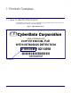
1 1 Product Overview 1.1 How to Identify This Product To identify the VoIP Intercom, look for a model number label similar to the one shown in Figure 1-1. The model number on the label should be 010935B. Figure 1-1. Model Number Label WWW.CYBERDATA.
Product Overview 2 Typical System Installation 1.2 Typical System Installation The Voice-over-IP (VoIP) Intercom is a SIP endpoint designed to provide VoIP phone connectivity in a tamper proof and secure package. Figure 1-2, Figure 1-3, and Figure 1-4 illustrate how the VoIP Intercoms can be installed as part of a VoIP phone system. Figure 1-2. Typical Installation—Door Entry/Access Control Figure 1-3.
Product Overview 3 Typical System Installation Figure 1-4. Typical Installation—Emergency Phone . Warning Electrical Hazard: The VoIP Intercom enclosure is not rated for any AC voltages. GENERAL ALERT Warning Electrical Hazard: This product should be installed by a licensed electrician according to all local electrical and building codes.
Product Overview 4 Product Features 1.3 Product Features Operations Guide 930242E ● SIP ● Dual speeds of 10 Mbps and 100 Mbps ● 802.
Product Overview 5 Supported Protocols 1.4 Supported Protocols The Intercom supports: ● SIP ● HTTP Web-based configuration Provides an intuitive user interface for easy system configuration and verification of Intercom operations. ● DHCP Client Dynamically assigns IP addresses in addition to the option to use static addressing. ● TFTP Client Facilitates Web-based firmware upgrades of the latest Intercom capabilities. ● RTP ● RTP/AVP - Audio Video Profile ● Audio Encodings PCMU (G.
Product Overview 6 Dimensions 1.7 Dimensions Figure 1-5. Dimensions—Size of Unit With Case 5.0 [127] 5.0 [127] 2.
Product Overview 7 Dimensions Figure 1-6. Dimensions—Size of Unit Without Case 5.000 3.700 3.270 5.000 1.830 4.200 4.
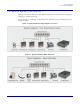
8 2 Installing the VoIP Intercom 2.1 Parts List Table 2-1 illustrates the SiP VoIP and PoE Speaker parts. Table 2-1.
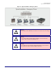
Installing the VoIP Intercom 9 Intercom Setup 2.1 Intercom Setup 2.1.1 VoIP Intercom Connections Figure 2-7 shows the pin connections on the J7 (terminal block). This terminal block can accept a wire range from 16 AWG to 26 AWG. Note As an alternative to using PoE power, you can supply 5 VDC at 1000 mA into the terminal block. Figure 2-7.
Installing the VoIP Intercom 10 Intercom Setup 2.1.2 Connecting a Device to the Auxiliary Relay The VoIP Intercom incorporates an on-board relay which enables users to control an external relay for activating an auxiliary device such as an electric door strike (see Figure 2-7). The Intercom relay contacts are limited to 1 amp at 30VDC. The Intercom relay activation time is selectable through the web interface and is controlled by DTMF tones generated from the phone being called.
Installing the VoIP Intercom 11 Intercom Setup 2.1.3 Identifying the VoIP Intercom Connectors See Figure 2-9, Figure 2-10, and Table 2-2 to identify the connectors and functions. Figure 2-9. J2, J5, and J6 Connector Locations Figure 2-10.
Installing the VoIP Intercom 12 Intercom Setup Figure 2-11. JP11—RTFM Switch Jumper See Table 2-2 for the connector settings. Table 2-2. Connector Settings Operations Guide Jumper Setting J1 PoE Network Connection (RJ-45 ethernet) J4 J-Tag (Factory only) J3 Terminal Block (see Figure 2-7) JP2 Call-Button/LED interface JP4 Reset (Factory only) JP5 Microphone Interface JP6 Speaker Interface JP8 Console (Factory only) JP11 RTFM (see Section 2.1.
Installing the VoIP Intercom 13 Intercom Setup 2.1.4 Call Button and Indicator Light 2.1.4.1 Initial Power Upon initial power or reset, you will see the following: • The light is on. • The light will blink twice to indicate that the Intercom has acquired its network settings and is operational. • The first blink indicates that the Intercom has acquired its network settings. • The second blink indicates that the Intercom is operational. 2.1.4.
Installing the VoIP Intercom 14 Intercom Setup 2.1.5 Network Connectivity, and Data Rate When you plug in the Ethernet cable or power supply: ● The square, green Link light above the Ethernet port indicates that the network connection has been established (see Figure 2-13 and Figure 2-14). The Link light changes color to confirm the auto-negotiated baud rate: • This light is yellow at 10 Mbps. • It is orange at 100 Mbps. Figure 2-13.
Installing the VoIP Intercom 15 Intercom Setup 2.1.5.1 Verify Network Activity The square, yellow Activity light blinks when there is network activity. Figure 2-14.
Installing the VoIP Intercom 16 Intercom Setup 2.1.6 RTFM Switch Jumper When the Intercom is operational and linked to the network, use the Reset Test Function Management (RTFM) switch (see Figure 2-15) on the Intercom board to announce and confirm the Intercom’s IP Address, test that the audio is working, and check the volume. Note You must do this test prior to final assembly. Please remember to remove the RTFM switch jumper prior to final assembly. Figure 2-15. RTFM Switch Jumper 2.1.6.
Installing the VoIP Intercom 17 Intercom Setup 2.1.6.2 Restore the Factory Default Settings When troubleshooting configuration problems, it is sometimes convenient to restore the device to a known state. Each Intercom is delivered with factory set default values. Use the RTFM switch on the Intercom face to restore these parameters to the factory default settings. To restore the factory default settings: 1. Complete steps 1 through 4 in Section 2.1.6.1, "Announcing the IP Address". 2.
Installing the VoIP Intercom 18 Configure the Intercom Parameters 2.1 Configure the Intercom Parameters To configure the Intercom online, use a standard web browser. Configure each Intercom and verify its operation before you mount it. When you are ready to mount an Intercom, refer to Appendix A, "Mounting the Intercom" for instructions.
Installing the VoIP Intercom 19 Configure the Intercom Parameters 2.1.1 Log in to the Configuration Home Page 1. Open your browser to the Intercom IP address. For the initial configuration of the Intercom, open your browser to the default IP address: http://192.168.3.10 Note Make sure that the PC is on the same IP network as the Intercom.
Installing the VoIP Intercom 20 Configure the Intercom Parameters 3. On the Home Page, review the setup details and navigation buttons described in Table 2-4. Table 2-4. Home Page Overview Web Page Item Description Device Name Shows the device name. Serial # Device serial number. Ethernet Address Device ethernet address. IP Addressing Shows the current IP addressing setting (DHCP or static). IP Address Shows the current IP address. Subnet Mask Shows the current subnet mask address.
Installing the VoIP Intercom 21 Configure the Intercom Parameters 2.1.2 Configure the Network Parameters 1. Click the Network Setup button to open the Network Setup page (Figure 2-18). Figure 2-18. Network Setup Page 2. On the Network Setup page, enter values for the parameters indicated in Table 2-5. Table 2-5. Network Setup Parameters Web Page Item Description IP Addressing* Select either DHCP IP Addressing or Static IP Addressing by marking the appropriate radio button.
Installing the VoIP Intercom 22 Configure the Intercom Parameters Table 2-5. Network Setup Parameters (continued) Web Page Item Description Link to the SIP Setup page. Link to the Upgrade Firmware page. Link to the Home page. 3. After changing the parameters, click Save Settings. This updates the changed parameters and reboots the Intercom if appropriate. 4. Connect the Intercom to the target network. 5.
Installing the VoIP Intercom 23 Configure the Intercom Parameters 2.1.3 Set up the Intercom 1. Click the Intercom Setup button to open the Intercom Setup page. See Figure 2-19. Figure 2-19.
Installing the VoIP Intercom 24 Configure the Intercom Parameters 2. On the Intercom Setup page, enter values for the parameters indicated in Table 2-6. Table 2-6. Intercom Setup Parameters Web Page Item Description Device Name Enter a descriptive name for this device (if desired).
Installing the VoIP Intercom 25 Configure the Intercom Parameters Table 2-6. Intercom Setup Parameters (continued) Web Page Item Description Link to the SIP Setup page. Link to the Sensor Setup page. Link to the Upgrade Firmware page. 3. After changing the parameters, click Save Settings.
Installing the VoIP Intercom 26 Configure the Intercom Parameters 2.1.4 Configure the SIP Parameters 1. Click SIP Setup to open the SIP Setup page (Figure 2-20). Note For specific server configurations, go to the VoIP Intercom product page at: http://www.cyberdata.net/support/voip/index.html Figure 2-20. SIP Setup Page 2. On the SIP Setup page, enter values for the parameters indicated in Table 2-7. Table 2-7.
Installing the VoIP Intercom 27 Configure the Intercom Parameters Table 2-7. SIP Setup Parameters (continued) Web Page Item Description Authenticate ID* Enter the Authenticate ID (up to 25 alphanumeric characters). Authenticate Password* Enter the Authenticate Password (up to 25 alphanumeric characters). SIP Registration* Enable/Disable SIP Registration. For information about the Point-to-Point Configuration, see Section 2.1.4.1, "Point-to-Point Configuration".
Installing the VoIP Intercom 28 Configure the Intercom Parameters 2.1.4.1 Point-to-Point Configuration When the board is set to not register with a SIP server (see Figure 2-21), it's possible to set the intercom to dial out to a single endpoint. In this case, the dial-out extension should be the IP address of the remote device. The Intercom can also receive Point-to-Point calls. The delayed DTMF functionality is available in the Point-to-Point Mode.
Installing the VoIP Intercom 29 Configure the Intercom Parameters 2.1.4.2 Delayed DTMF On the SIP setup page the dial out extension now supports the addition of comma delimited pauses and sending additional DTMF tones (using rfc2833). The first comma will pause three seconds after a call is first established with a remote device. Subsequent commas will pause for 2 seconds. A pause of one second will be sent after each numerical digit. Table 3.
Installing the VoIP Intercom 30 Configure the Intercom Parameters 2.1.5 Configure the Sensor Setup Parameters The door sensor (pins 5 and 6) on the header can be used to monitor a door's open or closed state. There is an option on the sensor setup page to trigger on an open or short condition on these pins. The door sensor alarm will be activated when the Door Open Timeout parameter has been met.
Installing the VoIP Intercom 31 Configure the Intercom Parameters 4. On the Sensor Setup page, enter values for the parameters indicated in Table 2-8. Table 2-8. Sensor Setup Parameters Web Page Item Description Door Sensor Flash Button LED* Select Yes to flash the LED until the sensor is deactivated (roughly 10 times/second). Activate Relay Select Yes to activate the relay until the sensor is deactivated.
Installing the VoIP Intercom 32 Upgrade the Firmware and Reboot the Intercom 2.1 Upgrade the Firmware and Reboot the Intercom To upload the Intercom firmware from your PC: 1. Set up a TFTP server. If you do not already have a TFTP server running on your network, see Appendix B, "Setting up a TFTP Server". 2. Retrieve the latest Intercom firmware from the VoIP Intercom product page at: http://www.cyberdata.net/support/voip/index.html 3. Unzip the Intercom version file.
Installing the VoIP Intercom 33 Upgrade the Firmware and Reboot the Intercom 7. Enter the IP address of your TFTP server into the TFTP Server IP parameter field. 8. Enter the firmware filename of the file to be uploaded into the New Filename parameter field. For example, kernel filename 201-image-spk-sip.bin. 9. Click Upload File. Note This starts the upload process.
Installing the VoIP Intercom 34 Upgrade the Firmware and Reboot the Intercom Table 2-9. Firmware Upgrade Parameters (continued) Web Page Item Description Link to the Home page. Click on this button to reboot the system.
Installing the VoIP Intercom 35 Upgrade the Firmware and Reboot the Intercom 2.1.1 Reboot the Intercom To reboot a Intercom, log in to the web page as instructed in Section 2.1.1, "Log in to the Configuration Home Page". 1. Click Upgrade Firmware to open the Firmware Upgrade page (Figure 2-24). Figure 2-24. Reboot System Section 2. Click Reboot. A normal restart will occur.
36 Appendix A: Mounting the Intercom A.1 Mount the Intercom Before you mount the Intercom, make sure that you have received all the parts for each Intercom. Refer to Table A-1. Table A-1.
37 Mount the Intercom To mount the Intercom: 1. Plug the Ethernet cable into the Intercom Assembly (see Figure A-1). Section 2.1.5, "Network Connectivity, and Data Rate" explains how the Link and Status LEDs work. Figure A-1.
38 Mount the Intercom 2. To fasten the Intercom: • For wall mounting, use the two 8-32 X 1/4" FLAT HEAD PHILLIPS MACHINE SCREW and the one 10-24 X 5/16" PAN HEAD PHILLIPS MACHINE SCREW to secure the Intercom. Figure A-1.
39 Mount the Intercom If the thread on the conduit is longer than 3/8 inch, then a stop nut (not supplied) is required. Otherwise, use the outlet box plug to plug the exit hole. Figure A-2. Mounting the VoIP Intercom Assembly HOLE PLUG OR CONDUIT Figure A-3 shows the restrictions of the conduit going into the box. Figure A-3. Conduit Restrictions Not to Exceed 0.
40 Mount the Intercom Figure A-4 shows how to properly mount the VoIP Intercom. Figure A-4.
41 Appendix B: Setting up a TFTP Server B.1 Set up a TFTP Server Upgrading the VoIP Intercom firmware requires a TFTP server on which you access the Web interface where you can upload the firmware files. B.1.1 In a LINUX Environment To set up a TFTP server on LINUX: 1. Create a directory dedicated to the TFTP server, and move the files to be uploaded to that directory. 2.
42 Appendix C: Troubleshooting/Technical Support C.1 Frequently Asked Questions (FAQ) A list of frequently asked questions (FAQs) are available on the VoIP Intercom product page at: http://www.cyberdata.net/support/voip/index.html Select the support page for your product to see a list of frequently asked questions for the CyberData product: C.2 Documentation The documentation for this product is released in an English language version only.
43 Warranty CyberData Corporation 2555 Garden Road Monterey, CA 93940 Attention: RMA "your RMA number" C.4 Warranty CyberData warrants its product against defects in material or workmanship for a period of two years from the date of purchase. Should the product fail within the warranty period, CyberData will repair or replace the product free of charge. This warranty includes all parts and labor.
44 Index Numerics D 100 Mbps indicator light 14 default gateway 18 intercom settings 44 IP address 18 subnet mask 18 username and password 18 web login username and password 19 default gateway 18, 21 default intercom settings 17 default IP settings 18 default login address 19 DHCP Client 5 DHCP IP addressing 21 dial out extension (door sensor) 31 dial out extension (intrusion sensor) 31 dial-out extension 27 support for comma delimited pauses 27 dial-out extension strings 29 dimensions 5, 6 discovery ut
45 M firmware upgrades 41 flash button LED (door sensor) 31 flash button LED (intrusion sensor) 31 microphone gain 20 mounting an intercom 36 G N green link light 14 network activity, verifying 15 network configuration of intercom 21 network rate 5 Network Setup 21 H home page 19 http web-based configuration 5 O I orange link light 14 outbound proxy 26 identifying your product 1 illustration of intercom mounting process 36 installation, typical intercom system 2 intercom configuration default IP
46 R T reboot 33, 35 register expiration 27 registration and expiration, SIP server lease 27 relay activate during ring 24 activate on button press 24 activation duration 24 on button press timeout 24 relay activation duration 24 relay on button press timeout 24 remote SIP port 26 remote SiP port 26 reset test function management switch 16 resetting the IP address to the default 36, 42 restoring factory default settings 17, 44 ringback tone configuration 24 RJ-45 12 RMA returned materials authorization 4