CYBERNET iONE-GX45 Series User Guide
FCC-B Radio Frequency Interference Statement This equipment has been tested and found to comply with the limits for a class B digital device, pursuant to part 15 of the FCC rules. These limits are designed to provide reasonable protection against harmful interference in a residential installation. This equipment generates, uses and can radiate radio frequency energy and, if not installed and used in accordance with the instruction manual, may cause harmful interference to radio communications.
Safety Instructions 1. 2. 3. 4. 5. 6. 7. 8. 9. 10. 11. 12. 13. Always read the safety instructions carefully. Keep this equipment away from humidity. Lay this equipment on a reliable flat surface before setting it up. The openings on the enclosure are for air convection hence protect the equipment from overheating. DO NOT COVER THE OPENINGS. Confirm the voltage of the power source and adjust accordingly to 110/220V before connecting the equipment to the power inlet.
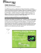
WEEE Statement (Waste Electrical and Electronic Equipment) The WEEE directive places an obligation on EU-based manufacturers, distributors, retailers and importers to take-back electronics products at the end of their useful life. A sister Directive, ROHS (Restriction of Hazardous Substances) compliments the WEEE Directive by banning the presence of specific hazardous substances in the products at the design phase. The WEEE Directive covers products imported into the EU as of August 13, 2005.
TABLE OF CONTENTS FCC-B Radio Frequency Interference Statement ........................................................ i Trademarks ..................................................................................................................... i Safety Instructions ........................................................................................................ ii WEEE Statement ..........................................................................................................
Installing the Optical Disk Drive .........................................................................................18 Installing the Mini-PCI Card (Optional) ...............................................................................20 Installing the Mini-PCIe Card (Optional) .............................................................................21 Installing the Cover..............................................................................................................
Introduction Congratulations for purchasing the iONE-GX45. The iONE-GX45 Series is your best Slim LCD PC choice. With the fantastic appearance and small form factor, it can easily be set anywhere. The feature packed platform also gives you an exciting PC experience. iONE-GX45 Series Specifications Processor Support Intel® Core™ 2 Duo and Core™ 2 Quad @ 1333MHz FSB in the LGA775 package up to 95W.
LCD Panel 17/19" TFT LCD panel Expansion Slots 2 mini-PCIe 1 mini PCI Front Lower Right Bezel On Screen Display Buttons Volume Adjust Brightness Adjust Contrast Adjust Mute/Exit Menu/Enter Right Side Bezel 1 power button 2 USB 2.0 ports (for mouse and keyboard) Left Side Bezel 1 optical disk drive – 2.5” slim Bottom I/O Panel 1 DC/IN port 2 Serial ports 1 DVI-I port 1 LAN RJ-45 jack 4 USB 2.
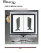
iONE-GX45 Series Overview Figure 1: Front View with Optional Webcam Cybernet iONE-GX45 Product Orientation Page 3
Figure 2: Left side view with Optical Drive Cybernet iONE-GX45 Product Orientation Page 4
Figure 3: Power Button and USB Ports Figure 4: Touch Panel Figure 5: IrDA Receiver for TV Tuner Cybernet iONE-GX45 Product Orientation Page 5
Figure 6: Front Bezel HDD & LAN LEDs On Screen Display Buttons There are six buttons on the lower right bezel of the screen. From left to right they are: Volume – Volume + Brightness – Contrast + Volume - Press to decrease volume. Volume + Press to increase volume. Mute/Exit Menu/Enter Brightness- Press first to select Brightness adjustment. Press again to decrease brightness. Press Contrast + to increase brightness. Brightness can also be adjusted in Menu Mode.
On Screen Display Usage When the Menu button is pressed, the on-screen display appears as pictured above. When in Menu Mode you can move to the various icons with the – (left) or + (right) button. When you are at the icon you wish to adjust, press Menu again (Enter) to change the color of the icon and then toggle your desired adjustment by again pressing either – (left) or + (right). The screen will exit automatically in a matter of seconds if no selection is made.
Figure 7: Back view Figure 8: Bottom Panel I/O Ports Cybernet iONE-GX45 Product Orientation Page 8
Figure 9: CPU Heat Sink Ventilation Fan Figure 10: System Ventilation Fan, System Ventilation and Stand Cybernet iONE-GX45 Product Orientation Page 9
System Assembly This chapter provides system assembly information and procedures. While performing any installation, use a grounded wrist strap before handling computer components and carefully follow all installation procedures. Static electricity may damage the components. This chapter will include instructions for how to install CPU, heat sink, memory modules, hard disk drive (HDD), optical disk drive (ODD), mini-PCI card, mini-PCIE card and IrDA module.
Orientation of Key Parts Figure 11: System Fan and Ventilation HDD and Optical Drive CPU Heat Sink Fan, Memory Modules, Mini-PCIe and Touch Panel Control.
iONE-GX45 Disassembly ORIENTATION: Presumes the top of the iONE is away from you and the bottom or I/O controller board is nearest you. 1. Place the iONE face down on a padded surface. 2. Remove the four screws from the base plate that attaches the stand to the LCD supporting the base while removing the last screw. 3. Remove the ten back bezel screws. 4. Carefully remove the back bezel and set aside. 5.
Installing the CPU NOTE: If you purchased your iONE-GX45 as a turn-key system, you must first follow the instructions to remove the heat sink in order to be able to reach the CPU. Systems purchased as ‘bare bones’ require the installation of the heat sink which is shipped in the accessories box with the unit. 1. The socket has a plastic cap on it to protect the pins from damage. This should remain in place until actually installing a CPU. 2.
Installing the CPU Heat Sink 1. Put on the heat sink and make sure that the four screws fit the corresponding screw holes on the mainboard. 2. Alternate pressure while securing the four screws with balance. Note: Do not fix any screws until the four screws are in their positions. 3. Secure the two screws at the opposite end near the top edge of the bezel. 4. Connect the power cable to CPU Fan on the Mainboard labeled FAN 1 CPU FAN.
Installing the Memory Module DDR3 SO-DIMM 1. The memory module has only one notch and will only fit in the slot one way. 2. Insert the memory module into the DIMM slot at a 45° angle. Then push it in until the golden finger on the memory module is deeply inserted in the DIMM slot. 3. Press the memory module down and the metal clip at each side of the DIMM slot will automatically close. 4. Repeat the steps to install another memory module to meet your needs.
Installing the Hard Disk Drive 1. Unscrew the four screws on the Optical Disk Drive frame (2 shown circled, 2 on opposite side) and remove the frame and disconnect the SATA cable from the mainboard and set aside in order to gain access to the Hard Disk Drive slot. Optical Disk Drive Frame Screws 2. Slide the hard disk drive into the frame and line up the two screw holes accordingly. Secure the two screws on the Hard Disk Drive. Connect the SATA cable to the mainboard. SATA Cable 3.
Installing the Optical Disk Drive 1. Remove back bezel as indicated in iONE Disassembly. Remove the Optical Disk Drive frame as indicated in Installing the Hard Disk Drive. 2. Put the ODD on the ODD frame and line up the four screw holes accordingly. 4. Secure the four screws on the ODD frame.
5. Connect the SATA cable. Connect the Power Cable. 6. Connect the other end of the cable to the ODD. 7. Install the ODD frame and line up the two screw holes over the stand-offs on the mainboard as well as the two screw holes on the side of the Hard Disk Drive slot. 8. Secure the four screws to fix the ODD frame and complete the installation.
Installing the Mini-PCI Card (Optional) 1. The mini-PCI card has only one notch and will only fit in one way. Insert the mini-PCI card into the miniPCI slot at a 45° angle. Then push it in until the golden finger on the miniPCI card is deeply inserted in the mini-PCI slot. 2. Press down the mini-PCI card and the metal clip at each side of the miniPCI slot will automatically close.
Installing the Mini-PCIe Card (Optional) 1. The mini-PCIE card has only one notch and will only fit in one way. Insert the mini-PCIe card into the mini-PCIe slot at a 45° angle. Then push it in until the golden finger on the mini-PCIe card is deeply inserted in the mini-PCIe slot. 2. Press down the mini-PCIe card and secure the screw to complete the installation.
Installing the Cover 1. Connect the power cable to System Fan on the mainboard before securing the metal cover with seventeen screws. 2. Secure the plastic cover with eleven screws. 3. Secure the stand with four screws.
Cybernet iONE-GX45 eWaste SOP USA Page 23
Cybernet e-recycling SOP For the recycling of Cybernet Branded Equipment Customer Notification Steps 1. Client learns of Cybernet Recycling Program via note card included with their ZPC/iOne purchase. 2. Client contacts Cybernet either by phone, email, or support request (pictured).
Cybernet e-recycling SOP For the recycling of Cybernet Branded Equipment Customer Notification Steps Steps: 1. Support Rep Enters Back for Recycling as Nature of Problem, enters serial number, then issues ticket 2. Support Rep marks ticket as 'Authorized for RMA;' if speaking with client will verbally confirm Ticket Number. If client has emailed or made request through the website, Support Rep will email Ticket to client. 3. Client will request RMA under Support section of www.cybernetman.
Cybernet e-recycling SOP For the recycling of Cybernet Branded Equipment Customer Notification Steps Steps Continued: 4. Client will be taken to RMA Request form; address will be confirmed. 5. Product is not being returned to customer; option defaults to no. 6. Client will click submit button at bottom of page to submit RMA Request. 7. Client's interaction ends with call to action screen; they are to await email with RMA Number, shipping label, and instructions on how to move forward.