
User Guide

Utility Tower Plus Series UPS
UP425UIT/UP550UI/UP750UI
User Manual
eu.cyberpowersystems.com
UNPACKING
Inspect the UPS upon receipt. The box should contain the following:
UPS Unit; PowerPanel Personal Edition Software Disk x 1; USB Cable x 1; Telephone Cable x 1;
IEC-IEC Power Cord x 2; UPS User Manual; Warranty Card.
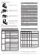
HOW TO DETERMINE THE POWER REQUIREMENTS OF YOUR EQUIPMENT
1. Insure that the equipment plugged into the battery power-supplied outlets does not exceed the UPS
unit’s rated capacity (425VA/255W for UP425UIT, 550VA/330W for UP550UI, 750VA/450W for UP750UI).
If rated unit capacities are exceeded, an overload condition may occur and cause the UPS unit to shut
down or the circuit breaker to trip.
2. If the power requirements of your equipment are listed in units other than Volt-Amps (VA), convert
Watts (W) or Amps (A) into VA by doing the calculations below. Note: The below equation only calculates
the maximum amount of VA that the equipment can use, not what is typically used by the equipment at
any one time. Users should expect usage requirements to be approximately 60% of below value.
TO ESTIMATE POWER REQUIREMENTS
1. Watts (W) x 1.6 = VA or Amps (A) x 230 = VA
2. Add the totals up for all pieces of equipment and multiply this total by 0.6 to calculate actual
requirements. There are many factors that can affect the amount of power that your computer system will
require. The total load that you will be placing on the battery-powered outlets should not exceed 80% of
the unit’s capacity.
HARDWARE INSTALLATION GUIDE
1. Connect the equipment to your UPS outlets. The IEC-IEC power cords coming with the unit are used to
connect your computer and monitor to the UPS. Items such as copiers, laser printers, vacuums, space
heaters, or other large electrical devices should not be connected to the UPS. Please make sure that the
total loads of your equipments are less than the maximum total power load of your UPS.
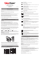
FRONT PANEL AND REAR PANEL DESCRIPTION
2. Use your computer power cord to connect the UPS to a wall outlet. Please avoid using extension cords
and adapter plugs. (To maintain optimal battery charge, leave the UPS plugged in at all times.)
3. Press the UPS power button to turn it on. The “Power On” indicator will be illuminated in “Green”.
4. Install your software and accessories. To use the software, simply connect the enclosed USB/Serial
interface cable to the USB/Serial port on the UPS and an open USB/Serial port on the computer.
The below contents are for UP550UI/UP750UI only!
CAUTION! Read and follow the IMPORTANT SAFETY INSTRUCTIONS before servicing the battery.
Service the battery under the supervision of personnel knowledgeable of batteries and their
precautions. Keep unauthorized personnel away from batteries. If you have questions, contact your
dealer or call the number in this manual for information on battery replacement.
CAUTION! Use only the specified type of battery. See your dealer for replacement batteries.
CAUTION! The battery may present the risk of electrical shock. Do not dispose of batteries in a fire,
as it may explode. Follow all local ordinances regarding proper disposal of batteries.
CAUTION! Do not open or mutilate the batteries. Release electrolyte is harmful to the skin and eyes
and may be toxic.
CAUTION! A battery can present a high risk of short circuit current and electrical shock. Take the
following precautions before replacing the battery:
1. Remove all watches, rings or other metal objects.
2. Only use tools with insulated handles.
3. DO NOT lay tools or other metal parts on top of battery or any battery terminals.
4. Determine if the battery is inadvertently grounded. If inadvertently grounded, remove source of ground.
CONTACT WITH A GROUNDED BATTERY CAN RESULT IN ELECTRICAL SHOCK! The likelihood of
such shock will be reduced if such grounds are removed during installation and maintenance
(applicable to a UPS and a remote battery supply not having a grounded circuit).
5. Batteries are consider HAZARDOUS WASTE and must be disposed of properly. Contact your local
government for more information about proper disposal and recycling of batteries.
6. Turn off and unplug all connected equipment.
7. Turn the UPS off and unplug it from the AC power source.
8. Turn the UPS upside down.
9. Note! The battery replacement is not available for UP425UIT.
Power Switch
Press the power button to turn the UPS ON or OFF.
Power On Indicator
This LED is illuminated when the utility condition is normal and the UPS outlets are providing
“clean power”, free of surges and spikes.
Using Battery Indicator
This illuminates during utility failure, indicating that the battery is supplying power to the
battery-power supplied outlets.
Replace Battery Indicator
The LED illuminates when the UPS battery is no longer useful and must be replaced.
Please see manual “Battery replacement procedure”.
Overload Indicator
The LED illuminates when the loads connected to the UPS exceed the UPS
capacity.
Battery Backup and Surge Protection Outlets
The UPS provides battery powered and surge protected outlets for connected equipment to
insure temporary uninterrupted operation during a power failure and against surges and
spikes.
Surge Protection Outlets
The UPS provides surge protected only outlet for connected equipments against surges and
spikes.
Fuse for Overload Protection
Fuse provide optimal overload protection. When overload occurs, the fuse will broken and
UPS switches to battery mode. You will need to change the spare fuse that provided with the
unit so the UPS will provide the power from utility.
USB Type B Port to PC
This Port allows connection and communication from USB port on the computer to the UPS
unit. The UPS communicates its status to the PowerPanel Personal Edition software. This
interface is also compatible with the UPS service provided by Windows
R
2000 and
Windows
R
XP.
Contact Closure Serial Port to PC
This port allows connection and communication from the DB-9 serial on the computer to the
UPS unit.
Note: Only one of the above two ports can be used to communicate with your computer at
one time.
Note: To install PowerPanel Personal Edition Software the computer will need Microsoft
R
Internet Explore 5.0 or higher installed.
Note: If using the Serial Port, users need to download PowerPanel
software from our
website http://www.cyberpower-eu.com and order the standard serial cable.
Ethernet (RJ-45/11) Network Protection Ports
These ports are used for the protection of your network devices from the surge and spike
through network cables.
Voltage Sensitivity Setting
These DIP switch setting is used for choosing the UPS input voltage sensitivity. The default
value is 180Vac ~ 266Vac which is used for most the computer systems and switching power
supply. The high sensitivity value is 196Vac ~ 256Vac which is used for some precision
instruments. And the low sensitivity value is 160Vac ~ 278Vac which is used for the wild
voltage power supplies.
K01-U425003-01
POWER
ON
USING
BATTERY
REPLACE
BATTERY
OVERLOAD
+
BATTERY
SURGE
SURGE
DEFAULT
DEFAULT
HIGH
LOW
160V~278V
180V~266V
180V~266V
196V~256V
OUT
IN
COMMUNICATION PORT
UP425UIT
POWER
ON
USING
BATTERY
OVERLOAD REPLACE
BATTERY
Output:1 220-240V~,50-60Hz
5A, 50-60 Hz, 1
Fuse:T6.3A, 250V~, 1
COMMUNICATION PORT
Input: 220-240V~
SURGE
OUT
BATTERY
+
IN
DEFAULT
DEFAULT
HIGH
LOW
160V~278V
180V~266V
180V~266V
196V~256V
SETTING
SENSITIVITY
VOLTAGE
SURGE
UP425UIT UP550UI/UP750UI
PLUG IN
PLUG IN
(SAVE THESE INSTRUCTIONS)
This manual contains important safety instructions. Please read and follow all instructions carefully during
installation and operation of the unit. Read this manual thoroughly before attempting to unpack, install, or
operate your UPS.
This equipment can be operated by any individuals with no previous training.
The socket-outlet shall be installed near the equipment and easily accessible.
During the installation of this equipment it should be assured that the sum of the leakage currents of the
UPS and the connected loads does not exceed 3.5mA.
Attention, hazardous through electric shock. Also with disconnection of this unit from the mains,
hazardous voltage still may be accessible through supply from battery. The battery supply should be
therefore disconnected in the plus and minus pole at the quick connectors of the battery when
maintenance or service work inside the UPS is necessary.
Do not dispose of batteries in a fire, the battery may explode.
Do not open or mutilate the battery or batteries, released electrolyte is harmful to the skin and eyes.
Do not replace the batteries of UP425UIT.
SAFETY WARNINGS
INSTALLING YOUR UPS SYSTEM
BASIC OPERATION
BATTERY REPLACEMENT AND STORAGE