User Manual Power Distribution Unit
Table of Contents Model List............................................................1 Introduction.........................................................1 Package Contents........................................................ 1 For 1U Series......................................................... 1 For 0U Series......................................................... 2 For 2U Series......................................................... 3 Safety Precautions.......................................
Model List 1U Switched Series 0U Monitored Series PDU15SW8FNET PDU15SWHVIEC8FNET PDU20SW8FNET PDU20SWT8FNET PDU20SWHVIEC8FNET PDU15MV16FNET PDU20MVT24FNET PDU20MVHVT24FNET PDU30MVT24FNET PDU30MVHVT24FNET 1U Monitored Series 2U Switched Series PDU15M8FNET PDU15MHVIEC8FNET PDU20M8FNET PDU20MT8FNET PDU20MHVIEC8FNET PDU30SWT16FNET PDU30SWHVT16FNET 2U Monitored Series PDU30MT16FNET PDU30MHVT16FNET 0U Switched Series PDU15SWV16FNET PDU20SWVT24FNET PDU20SWVHVT24FNET PDU30SWVT24FNET PDU30SWVHVT24FNET Intr
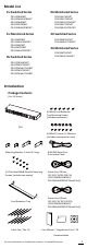
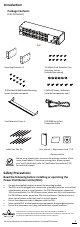
Introduction Package Contents (For 0U Series 16 Outlets/24 Outlets) PDU Cord Retention Tray Mounting Screws (M3x6)/Qty. 10 for 16 Outlets/Qty. 14 for 24 Outlets (Includes two spares) Mounting Brackets x 2 6 (M5x12) Screws/6 Washers (Includes two spares for each) 6 (Flat Head M4x4) Bracket Mounting Screws (Includes two spares) 2 Keyhole Mounting Pegs with 4 (M4x5) Screws (Includes two spares) Cord Retention Trays Qty. 2 (16 Outlets)/Qty.
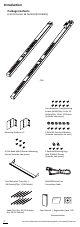
Introduction Package Contents (For 2U Series) PDU Mounting Brackets x 2 10 (M3x6) Cord Retention Tray Mounting Screws (Includes two spares) 10 (Flat Head M4x8) Bracket Mounting Screws (Includes two spares) 6 (M5x12) Screws / 6 Washers (Includes two spares for each) Cord Retention Trays x2 RJ45/DB9 Serial Port Connection Cable Cybe rPow er Reliab R ility. Qualit y. Value. User's Cable Ties: Qty.
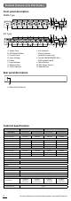
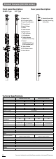
Product Features (1U 15A Series) Front panel description NEMA Type IEC Type A. Power Cord B. AC Output Outlets C. Current Level D. Input Voltage E. Power F. Load Indicator G. Ethernet Port H. Tx/Rx Indicator I. Link Indicator J. Outlet Indicator (switched series only) K. Serial/ ENVIROSENSOR Port (RJ45 modular port) L. Select Button M.PDU Status Screen N. Reset Button Rear panel description A A A.
Product Features (1U 20A Series) Front panel description NEMA Type IEC Type A. Power Cord B. AC Output Outlets C. Current Level D. Input Voltage E. Power F. Load Indicator G. Ethernet Port H. Tx/Rx Indicator I. Link Indicator J. Outlet Indicator (switched series only) K. Serial/ ENVIROSENSOR Port (RJ45 modular port) L. Select Button M.PDU Status Screen N. Reset Button Rear panel description A A A.
Product Features (0U 15A Series) Front panel description Rear panel description A. Power Cord B. AC Output Outlets C. Current Level D. Input Voltage E. Power F. Load Indicator G. Ethernet Port H. Tx/Rx Indicator I. Link Indicator J. Outlet Indicator (switched series only) K. Serial / ENVIROSENSOR Port (RJ45 modular port) L. Select Button M. PDU Status Screen N. Reset Button A. Bracket Screw Hole B.
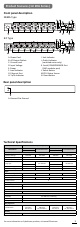
Product Features (0U 20A Series) Front panel description NEMA Type Rear panel description IEC Type B A. Power Cord B. AC Output Outlets C. Current Level D. Input Voltage E. Power F. Load Indicator G. Ethernet Port H. Tx/Rx Indicator I. Link Indicator J. Outlet Indicator (switched series only) K. Serial / ENVIROSENSOR Port (RJ45 modular port) L. Select Button M. PDU Status Screen N. Reset Button A A. Bracket Screw Hole B.
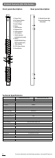
Product Features (0U 30A Series) Front panel description NEMA Type Rear panel description IEC Type B A. Power Cord B. AC Output Outlets C. Input Circuit Breaker D. Current Level E. Input Voltage F. Power G. Load Indicator H. Ethernet Port I. Tx/Rx Indicator J. Link Indicator K. Outlet Indicator (switched series only) L. Serial / ENVIROSENSOR Port (RJ45 modular port) M. Select Button N. PDU Status Screen O. Reset Button A A. Bracket Screw Hole B.
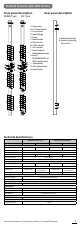
Product Features (2U Series) Front panel description NEMA Type C G B H Bank 1 , 20A 100-120VAC 50/60 Hz 24A MAX 2 1 Bank 2 , 20A 8 7 6 5 4 3 YU0-0000028-00 B1 B2 - Normal - Warning - Overload Amps Volts Tx/Rx I Link J Select KW 9 10 11 12 13 14 15 16 Reset K A D F E N O M IEC Type L C G B 2 1 200-240VAC 50/60 Hz 24A MAX 12A MAX PER OUTLET 8 7 6 5 4 3 YU0-0000028-00 H Bank 1 , 15A Bank 2 , 15A B1 B2 - Normal - Warning - Overload Amps Volts Tx/Rx
Installation Guide Please use only the provided screws through the entire installation process. Horizontal Installation For 1U Model Step 1. Mounting Bracket Installation Use the provided Mounting Bracket Screws (8) to attach the SHORT Mounting Brackets (2) to the PDU. If you plan on attaching the Cord Retention Tray to the PDU, you will need to use the LONG Mounting Brackets (2). Step 2. PDU Mounting Use the supplied Washers (4) and Screws (4) to secure the PDU to your existing rack system.
Installation Guide Step 3. Cord Retention Tray Installation (optional) Attach the Cord Retention Tray to the PDU with the 4 supplied Cord Retention Tray Mounting Screws. Use the provided Cable Ties to fasten each cord to the Cord Retention Tray. For 2U Model Step 1. Mounting Bracket Installation Use the provided Mounting Bracket Screws (8) to attach the Mounting Brackets (2) to the PDU. For more information on CyberPower products, visit www.CPSww.
Installation Guide Step 2. PDU Mounting Use the supplied Washers (4) and Screws (4) to secure the PDU to your existing rack system Step 3. Cord Retention Tray Installation (optional) Attach the Cord Retention Tray to the PDU with the 8 supplied Cord Retention Tray Mounting Screws. Use the provided Cable Ties to fasten each cord to the Cord Retention Tray. 12 For more information on CyberPower products, visit www.CPSww.
Installation Guide Vertical Installation For 1U Model Step 1. Mounting Bracket Installation Use the provided Mounting Bracket Screws (8) to attach the SHORT Mounting Brackets (2) to the PDU. Step 2. PDU Mounting Use the supplied Washers (2) and Screws (2) to secure the PDU to your existing rack system. For 0U Model with Bracket Step 1. Mounting Bracket Installation Use the provided Mounting Bracket Screws (4) to attach the Mounting Brackets (2) to the PDU.
Installation Guide Step 2. PDU Mounting Use the supplied Washers (2) and Screws (2) to secure the PDU to your existing rack system. Step 3. Cord Retention Tray Installation (optional) Attach the Cord Retention Tray to the PDU with the supplied Cord Retention Tray Mounting Screws. Use the provided Cable Ties to fasten each cord to the Cord Retention Tray. 14 For more information on CyberPower products, visit www.CPSww.
Installation Guide For 0U Model with Keyhole Mount Step 1. Keyhole Mount Installation Use the provided Screws (2) to attach the Keyhole Mounting Pegs (2) to the PDU. Step 2. PDU Mounting Align the Keyhole Mounts to the Keyhole Slots on the rack. Insert and slide down to lock firmly into the place. Electrical Installation Step 1 – Receptacle evaluation Ensure that the plug type of your PDU unit matches the wall receptacle type that you are using.
Installation Guide Step 3 – Attach equipment It is extremely important not to exceed the PDUs maximum current load (as outlined in the Specifications section). In order to determine your total load, simply use the Metered Readout on the front of the PDU. Network Installation Step 1 – Attach the LAN Cable Using a CAT5 RJ45 cable, attach one end to the Ethernet port on the front of the PDU, and the other end to a network port.
Installation Guide 4. Type “setup” and press Enter to enter the Authentication menu. 5. Enter the user name and password of the PDU device at the Authentication menu. Note: The default username is “cyber” and the default password is “cyber”. For further information and configuration via Hyper Terminal, see Appendix A-Hyper Terminal.
Operation Environmental Monitoring (optional) CyberPower PDUs along with the environment sensor (ENVIROSENSOR) provide the function of temperature and humidity monitoring in a server closet and/ or datacenter remotely. To connect the PDU with ENVIROSENSOR, use the RJ45 Ethernet Cable. Plug one end into the Serial/ENVIROSENSOR port on the PDU and the other end into the RJ45 port on the ENVIROSENSOR (as shown in figures below).
Operation Unattended/Automatic Shutdown PowerPanel Business Edition software automatically intitiates a graceful shutdown on the operating system in an orderly fashion. PowerPanel must be installed on every PC for which the shut down is to take place. The PC receives SNMP messages directly from the PDU, and these messages can be scheduled for an exact date/time, or can be performed immediately. Follow the directions below for setting up Unattended/Automatic Shutdown. Step 1. PC Configuration 1.
Troubleshooting Problem PDU outlets do not provide power to connected equipment Possible Cause 1. Breaker tripped 2. Loose power cord Solution Reset Breaker, check if plug is completely connected. If the problem remains, contact tech support. Amperage displayed 1. Overload The load indicator shows red on Metered Readout when overload. Reduce the load exceeds the units on the PDU until the overload capability is gone. If the problem remains, contact technical support. Circuit breakers have 1.
Customer Service & Warranty • Product Registration Thank you for purchasing a CyberPower product. Prompt product registration entitles coverage under the Limited Warranty, and also allows the opportunity to be notified of product enhancements, upgrades, and other announcements. Registration is quick and easy at www.cpsww.com/support/warranty-registration.html • CyberPower International Feel free to contact our Tech Support department with installation, troubleshooting, or general product questions.
Customer Service & Warranty What Are The Limitations? 1. This Warranty does not apply unless the Product and the equipment that was connected to it were connected to properly wired and grounded outlets (including compliance with electrical and safety codes of the most current electrical code), without the use of any adapters or other connectors. 2.
Appendix B-Power Device Network Utility • Overview The CyberPower Power Device Network Utility is an easy-to-use interface which is used for establishing IP addresses on CyberPower PDU devices. • Installation Step 1. Insert the CD labeled “PDU Software Installation CD” into the CD/DVD drive. Step 2. Select Power Device Network Utility from the installation menu (Shown in Figure 1.). Figure 1. Installation Menu Step 3. Select Next in the software wizard. Step 4.
Appendix B-Power Device Network Utility • Launch Program To launch the Power Device Network Utility and get started, select Programs from the Start menu in Windows and locate the new folder and icons for Power Device Network Utility. Select Power Device Network Utility from the program folder (Shown in Figure 3.). Figure 3. Power Device Network Utility • Getting Started The Power Device Network Utility scans the network for devices with MAC addresses that match CyberPower network hardware.
Appendix B-Power Device Network Utility Step 2. Assign a valid IP Address to the PDU Option 1: Assisted Setup (recommended) With the appropriate device selected from the Equipment List, open the Network Settings menu (Shown in Figure 6.). [Tools=>Device Setup]. In the Device Network Setting Menu, enter a valid IP address, subnet mask, and gateway address to setup the PDU device. Figure 6. Network Setting Menu (Device Setup) Note: The DHCP option is not available for all power devices. Step 3.
CyberPower Systems, Inc. www.CPSww.