User’s Manual BATTERY PACK BP36V60ART2U BP72V60ART2U CyberPower Systems (USA), Inc. 4241 12th Avenue East Suite 400 Shakopee, MN 55379 Phone: 877-297-6937 Fax: 952-403-0009 www.CPSww.
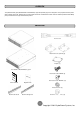
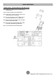
OVERVIEW The CyberPower Battery packs (BP36V60ART2U / BP72V60ART2U) support 50A polarized plugs, and are designed for variety of CyberPower UPS systems. When combining with the UPS, the Battery pack provides extended runtime with a 36VDC/72VDC external connection. Additional parallel-connected Battery packs provide the UPS for a longer extended runtime operation. UNPACKING Power cord Rackmount ears (Stands) (2) Tie plate (1) 1K/1.
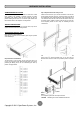
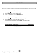
HARDWARE INSTALLATION HARDWARE INSTALLATION Step 3: Adjust rackmount rails to fit your rack These versatile Battery packs can be mounted in a rackmount or vertical tower orientation. This versatility is especially important to growing organizations with changing needs that value having the option to position a Battery pack on a floor or in a rackmount system. Please follow the instructions below for the respective mounting methods.
HARDWARE INSTALLATION VERTICAL/TOWER INSTALLATION Step 1: Rotate the Multifunction LCD Module Step 2: Attach the base stands Unscrew the right panel of the UPS. Separate the right panel from the UPS. Gently lift the LCD module out. Rotate it to the tower orientation. Reinstall it for a tower configuration. Secure the tie bracket with the screws (M5X8*4pcs). Tighten the screws (M5X12*4pcs) of the base stands (rackmount ears) onto the bottom of the UPS and the Battery pack.
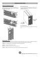
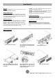
BASIC OPERATION BATTERY PACK FRONT/REAR PANEL DESCRIPTION 1. On-board Replaceable Fuse Cover Replaceable fuse is accessible from the rear panel. It must be done by qualified personnel. 2. AC Circuit Breaker Provides overload and fault protection. 3. AC Output Outlet Use this outlet to connect to the AC Input Inlet of a downstream Battery pack. 4. AC Input Inlet (Charge Only) AC power connectivity to wall receptacle. 5. Input Connector Use this input connector to daisy chain the next Battery pack.
BASIC OPERATION CONNECTION #2 : UPS WITH MULTIPLE BATTERY PACKS Step 1: Connect the 1st Battery pack to the UPS using the instructions above. Step 2: Turn off the DC breaker of the 2nd Battery module. Step 3: Loosen the two screws to remove the battery cable retention bracket of the 1st battery pack. Step 4: Use the output cable of the 2nd Battery pack to connect the 2nd Battery pack to the 1st Battery pack. Step 5: Rotate the battery cable retention bracket and tighten the two screws to fix battery cable.
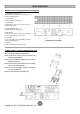
BASIC OPERATION EXTERNAL BATTERY PACKS CONFIGURATION The UPS can be configured to reflect the correct estimated run-times for the number of battery packs installed by using the LCD Control Panel to select the number of battery packs installed. 1. Press the “ENTER” button to activate the “MAIN MENU”. 2. Press the “▲” and “▼” buttons to scroll to the “Configure” option. 3. Press the “ENTER” button to select the “Configure” submenu. 4.
MAINTENANCE CAUTION! Do not open or mutilate the batteries. Electrolyte fluid is harmful to the skin/eyes and may be toxic. CAUTION! To avoid electric shock, turn off and unplug the Battery pack from the wall receptacle before servicing the battery. CAUTION! Only use tools with insulated handles. Do not lay tools or metal parts on top of the UPS or battery terminals. Storage To store your Extended Battery Packs for a long period of time, cover it and store with the batteries fully charged.
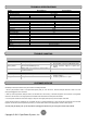
TECHNICAL SPECIFICATIONS Model Configuration AC Input Voltage DC Output Voltage Amperage Physical Dimensions (L x W x H =) Net Weight Battery Specifications Recharge Time (Typically) Interface Sealed, Maintenance Free Hot-Swappable Built-in Charger Environment Operating Temperature Operating Relative Humidity Safety Conformance Approvals RoHS Warranty Product Warranty BP36V60ART2U BP72V60ART2U 100~125Vac 36Vdc 72Vdc 60A 16.9 x 17 x 3.5in. (430 x 433 x 88mm) 50.6lbs(23.0Kg) 23.6 x 17 x 3.5in.
PRODUCT REGISTRATION CyberPower requests that you complete and return the Warranty Registration Card enclosed with the Product or register the Product at its website (www.cpsww.com) to establish that you are the Initial Customer of the Product, and therefore entitled coverage under the Limited Warranty and the Connected Equipment Guarantee. (Registration is not required for coverage, but note: if you do not register your purchase, you will be required to provide proof of purchase.
LIMITED WARRANTY AND CONNECTED EQUIPMENT GUARNTEE Who Pays For Shipping? We pay when we send items to you; you pay when you send items to us. What Are Some Examples Of What This Warranty Does Not Cover? 1. This Warranty does not cover any software that was damaged or needs to be replaced due to the failure of the Product or any data that is lost as a result of the failure or the restoration of data or records, or the reinstallation of software. 2.
CONFORMANCE APPROVALS FCC Notice This device complies with part 15 of the FCC Rules. Operation is subject to the following two conditions: (1) This device may not cause harmful interference, and (2) this device must accept any interference that may cause undesired operation. WARNING!! This equipment has been tested and found to comply with the limits for a Class A digital device, pursuant to part 15 of the FCC Rules.