User’s Manual BPE48V75ART2U Battery Pack K01-0000127-01
Table of Contents OVERVIEW 2 PRODUCT FEATURES 2 TECHNICAL SPECIFICATIONS 3 INSTALLATION INSTRUCTIONS 4 Package Contents 4 HARDWARE INSTALLATION GUIDE 5 Safety Precautions 5 Rackmount Installation 5 Vertical/Standing Installation 7 ELECTRICAL INSTALLATION GUIDE 8 BATTERY PACK CONFIGURATION 9 TROUBLE SHOOTING 11 NEED ADDITIONAL HELP 11 1 Copyright © 2009 CyberPower Systems, Inc.
Overview The CyberPower BPE48V75ART2U Battery Pack provides extended runtime (XL) for the PR1000ELCDRTXL2U, PR1500ELCDRTXL2U, PR2200ELCDRTXL2U and PR3000ELCDRT2U. The 2U BPE48V75ART2U Battery Pack matches the esthetics of these UPSs, and can be used in either rack or tower installations. The heavy gauge power cord has a plug-n-play DC connector for easy installation. The all metal enclosure safely houses eight 12V 9Ah batteries (The specified type of battery: HR9-12 FR (BB)).
Technical Specifications General Model BPE48V75ART2U Input Nominal Input Voltage 48 VDC, 230VAC Overload Protection AC, DC circuit protection Batteries Specifications (8 of batteries) 12V/ 9.0AH Sealed Maintenance Free Yes User Replaceable Yes Battery Life 3-5 Years Compatibility UPS Compatibility PR1000/1500/2200ELCDRTXL2U, PR3000ELCDRT2U Scalability Battery Packs Unlimited (Up to 5 for PR3000ELCDRT2U) Charging Built-in Charger Yes Physical Dimensions (cm) 2U Rack, 43.3 x 8.
Installation Instructions Package Contents Rack-mount Ear Screws (14) Battery Pack Unit 把把 個 Rack-mount Handles (2) Rack-mount Ears (2) Rackmount Rails (1 set – Left and Base Stand Extensions (2) Right sides) Rack-mount Handle Screws (5) Rackmount Rail Screws (6) Screw Hole Dust Covers (5) Screw Hole Dust Cover Screws (5) User’s Manual Auxiliary AC Power Cord Copyright © 2009 CyberPower Systems, Inc.
Hardware Installation Guide Safety Precautions CAUTION! Before connecting the Battery Pack(s) to the UPS, completely turn off and unplug the main UPS from the wall receptacle. CAUTION! Do not disconnect the any Battery Packs when the UPS is turned on or plugged into a wall receptacle. CAUTION! Do not connect the battery pack into itself. CAUTION! Do not add more Battery Packs to the UPS than is specified in the Technical Specifications section of the User’s Manual.
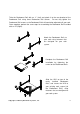
Take the Rackmount Rail with an “L” (Left) and attach it to the rear bracket of the Rackmount Rail using three Rackmount Rail Screws. Do not fully tighten the Rackmount Rail screws, as the Rackmount Rails will need to be adjusted to fit your rack. Once complete, perform the same steps for assembling the Rackmount Rail inscribed with an “R” (Right). Attach the Rackmount Rails to your rack using fasteners that are designed for your rack system.
Vertical/Standing Installation Step 1: Expand Base Stands Remove the UPS from the Base Stands, and separate the Base Stands to make room for the Base Stand Expanders. Take the Base Stand Expanders and insert them in-between the separated Base Stands. Be sure the pieces firmly snap together. Step 2: Install Battery Pack Insert Dust Covers into the Rackmount Ear screw holes that are not being used. The UPS and Battery Pack should now fit easily in the newly expanded Base Stands.
Electrical Installation Guide CAUTION! Before connecting the Battery Pack(s) to the UPS, completely turn off and unplug the main UPS from the wall receptacle. CAUTION! Do not disconnect the any Battery Packs when the UPS is turned on or plugged into a wall receptacle. CAUTION! Do not connect the battery pack into itself. CAUTION! Do not add more Battery Packs to the UPS than is specified in the Technical Specifications section of the User’s Manual.
Step 3: Connect the Battery Pack to wall power Plug the female end AC Power Cord into the Battery Pack, and plug the male end into a wall receptacle or PDU. Note: Do NOT plug this AC Power Cord into a UPS. If using multiple Battery Packs, use the Auxiliary AC Power Cord to provide power to subsequent power to additional Battery Packs.
Step 2: Configure the UPS to recognize the Battery Packs Press the Select button until the UPS displays a screen that shows a number (0-10) with an “A” suffix. The number 0-10 indicates how many battery packs are attached. The default is zero. To change this number, press and hold the Select button for four seconds. Now, simply press the Select button and change the number to match how many Battery Packs you have attached to the UPS.
Trouble Shooting Problem Possible Cause Solution By pressing the display toggle to The UPS LCD does Do not set the UPS select functions. Then, set up the not perform to recognize the correct battery pack numbers. The expected runtime. battery pack(s). default setting is 0. Allow the battery pack to charge for 24 hours. Do not expect full runtime Batteries are not during this initial charge period. fully charged. Specified battery pack models can use AC to shorten charge time.