CPS3000PIE USER MANUAL K01-0000010-00
CPS3000PIE TABLE OF CONTENTS SAFETY AND EMC INSTRUCTIONS………….……………………………………….………1 INSTALLING YOUR EPS………………………….………………………………….……3 BASIC OPERATION…………………………………………...................................................4 REPLACING THE BATTERY…………………….……………………………………….…...….6 DEFINITIONS FOR ILLUMINATED LCD………….……………………………………7 EPS STATUS INQUIRY AND FUNCTIONS SETUP…….……………………………………8 FAULT WARNING DISPLAY AND ALARM……………………………………….………10 TROUBLESHOOTING…………………………………………………….............................
CPS3000PIE K01-0000010-00 SAFETY AND EMC INSTRUCTIONS (SAVE THESE INSTRUCTIONS) This manual contains important safety instructions. Please read and follow all instructions carefully during installation and operation of the unit. Read this manual thoroughly before attempting to unpack, install, or operate your Emergency Power System (EPS). CAUTION! To prevent the risk of fire or electric shock, install in a temperature and humidity controlled indoor area free of conductive contaminants.
CPS3000PIE DO NOT USE FOR MEDICAL OR LIFE SUPPORT EQUIPMENT! DO NOT use in any circumstance that would affect operation or safety of any life support equipment or with any medical applications or patient care. DO NOT USE WITH OR NEAR AQUARIUMS! To reduce the risk of fire or electric shock, do not use with or near an aquarium. Condensation from the aquarium can cause the unit to short out. DO NOT USE WITH LASER PRINTERS! The power demands of these devices will overload and possibly damage the unit.
CPS3000PIE INSTALLING YOUR EPS UNPACKING Inspect the EPS upon receipt. The box should contain the following: EPS unit x1; Installation Guide x1; User manual x1; Warranty card x1. AUTOMATIC VOLTAGE REGULATOR Utility power is inconsistent. The EPS increases low voltage to computer safe 220 volts. The EPS automatically provides battery backup (External battery connection required) if the voltage drops below 140 volts or exceeds 300 volts. HARDWARE INSTALLATION GUIDE 1.
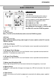
CPS3000PIE BASIC OPERATION DESCRIPTION 1. AC Outlets The unit has two Schuko outlets and one terminal for connected equipment which ensures temporary uninterrupted operation of your equipment during a power failure. Max. output of 1a is 20A; Max. output of 1b is 15A; Max. output wattage of (1a+1b) is 2250W Note:Maximum cord length is 10 meters and the cable O.D. must be 12AWG or greater. 2. AC Inlet AC input terminals Note:The O.D. of the distribution cables must be 12AWG or greater. 3.
CPS3000PIE 10. Power On Indicator This LED is above the power switch. It illuminates when the utility condition is normal and the EPS outlets are providing power, free of surges and spikes. 11. LCD Module Display High resolution and intelligent LCD display shows all the EPS information with icons and messages. For more information please check the DEFINITIONS FOR ILLUMINATED LCD INDICATORS section. 12. LCD Display Toggle / Selected Switch Users can monitor EPS status and set up functions using the toggle.
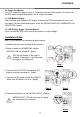
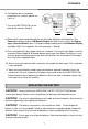
CPS3000PIE 6. If the battery box or the battery connection has a switch, please turn it on first. 7. Turn on the BATTERY SW. on the back of the machine (Step 5) Step 5 Step 6 8. Make the AC input connection and turn on the Power Switch on the front panel. The Power On Indicator and the LCD Module Display will blink 4 times. Press the Display toggle (Selected Switch) once. The output voltage showing on the LCD Module Display should be 220V. This completes the start-up process. (Step 6) 9.
CPS3000PIE CAUTION! A battery can present a high risk of short circuit current and electrical shock. Take the following precautions before replacing the battery: 1. Remove all watches, rings or other metal objects. 2. Only use tools with insulated handles. 3. Do not lay tools or metal parts on top of battery or any terminals. 4. Wear rubber gloves and boots. 5. Determine if the external battery is inadvertently grounded. If grounded, remove the source of ground.
CPS3000PIE 6. SILENT MODE Icon: This icon illuminates whenever the EPS is in silent mode. The buzzer will not beep during the battery mode until the battery reaches low capacity. 7. OVER LOAD Icon: This icon will illuminate and an alarm will sound to indicate the battery supplied outlets are overloaded. To clear the overload, unplug some of your equipment from the battery supplied outlets until the icon is no longer illuminated and the alarm stops. 8.
CPS3000PIE 2. Set-up Mode Step 1 : The machine enters Set-Up Mode after holding the Display toggle for 10 seconds. Icon 4,5,6,7,8,9 lights to indicate Set-Up Mode. Step 2 : By pressing the Display toggle, users can switch between setup functions. User configurable functions are as follows: a. Delay Time: The time delay between switching from Battery Mode to Line Mode. There are 9 different settings. The default setting is 2.0 minutes.
CPS3000PIE Step 3: Press and hold the toggle for 4 seconds. When the icons blink, the value of each item can be changed by slightly pressing the toggle. Step 4: To save the value and return to general mode, press and hold the toggle for 4 seconds. Note: If the machine is left idle for over 30 seconds during setup, it will turn off the backlight and return to general mode automatically. Note: If user wants to return to general mode without saving changes, there are two methods: 1.
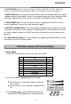
CPS3000PIE Battery Icon Flash Beep Once Fault Icon 1. Rapid Beep 2. Recurring Beep 3. Long Beep Can Not Start Up None Battery Missing- In Line Mode Battery Missing. 1. Low Battery Output-Off -- Insufficient battery capacity. 2. Over Charge or AVR Error-- In Line Mode, battery is overcharged or AVR is faulty. 3. Short Output-Off -Output Short Circuit Protection 1. Line Input/Output Error Output-Off -incorrect Input/Output connection 2.
CPS3000PIE TECHNICAL SPECIFICATIONS Model Capacity (VA) Capacity (Watts) Operation Technology AC Input Input Voltage Range Input Frequency Range AC Output Number of Phase On Battery Typical Output Voltage Nominal Output Voltage Configuration Note On Battery Output Frequency Overload Protection CPS3000PIE 3000VA 2250W AVR ( Single Boost & Single Buck ) 140Vac – 300Vac 50/60 Hz +/- 3 Hz (auto sensing) Single Phase Pure Sine Wave at 220Vac +/- 10% Configurable for 220 : 230 : 240Vac 50 / 60 Hz +/- 1% On Util