User’s Manual CPS600E CyberPower Europe CyberPower Systems B.V. Flight Forum 3545, 5657DW Eindhoven, The Netherlands Tel: +31 (0)40 2348170 Fax: +31 (0)40 2340314 Website: http://eu.cyberpowersystems.com/ E-mail: sales@cyberpower-eu.
CPS600E Content SAFETY AND EMC INSTRUCTIONS ................................... 2 INSTALLING YOUR EPS ...................................................... 4 UNPACKING ......................................................................................... 4 AUTOMATIC VOLTAGE REGULATOR ............................................... 4 HARDWARE INSTALLATION GUIDE ................................................... 4 BASIC OPERATION ..............................................................
CPS600E SAFETY AND EMC INSTRUCTIONS This manual contains important safety instructions. Please read and follow all instructions carefully during installation and operation of the unit. Read this manual thoroughly before attempting to unpack, install, or operate your Emergency Power System (EPS). CAUTION! To prevent the risk of fire or electric shock, install in a temperature and humidity controlled indoor area free of conductive contaminants.
CPS600E SAFETY: EN62040-1-1 EMI: Conducted Emission: IEC/EN 62040-2…Category C2 Radiated Emission: IEC/EN 62040-2……Category C2 Harmonic Current: IEC/EN61000-3-2 Voltage Fluctuations and Flicker: IEC/EN61000-3-3 EMS: IEC/EN61000-4-2(ESD) IEC/EN61000-4-3(RS) IEC/EN61000-4-4(EFT) IEC/EN61000-4-5(lightning surge) IEC/EN61000-2-2 (Immunity to low frequency signals) 3 Copyright © 2010 CyberPower Systems, Inc.
CPS600E INSTALLING YOUR EPS UNPACKING Inspect the EPS upon receipt. The box should contain the following: EPS unit x 1; User manual x 1; Input Power Cord x 1; DC Fuse x 2 AUTOMATIC VOLTAGE REGULATOR Utility power is inconsistent. The EPS increases low voltage to computer safe 220 volts. The EPS automatically provides battery backup (External battery connection required) if the voltage drops below 170 volts or exceeds 270 volts. HARDWARE INSTALLATION GUIDE 1.
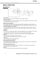
CPS600E BASIC OPERATION DESCRIPTION 1. Power Switch Used as the master on/off switch for equipment connected to the AC outlet. 2. Power On Indicator This LED is above the power switch. It illuminates when the utility condition is normal and the AC outlet is providing power, free of surges and spikes. 3. Multifunction LCD Readout High resolution and intelligent LCD display shows all the EPS information with icons and messages.
CPS600E REPLACING THE BATTERY CAUTION! Read and follow the IMPORTANT SAFETY INSTRUCTIONS before servicing the battery. Battery service should only be done by qualified professionals. CAUTION! Use only the specified type and number of external batteries. Please see the technical specifications for replacement batteries. CAUTION! The battery may present a risk of electrical shock. Do not dispose of battery in a fire as it may explode. Follow all local ordinances regarding proper disposal of batteries.
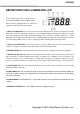
CPS600E DEFINITIONS FOR ILLUMINATED LCD The LCD Display indicates a variety of EPS operational conditions. All descriptions apply when the EPS is plugged into an AC outlet and turned on or when the EPS is on battery. 1. INPUT VOLTAGE Meter: This meter measures the AC voltage that the EPS is receiving from the utility wall outlet. The EPS is designed, through the use of automatic voltage regulation, to continuously supply connected equipment with stable, 220 output voltage.
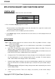
CPS600E EPS STATUS INQUIRY AND FUNCTIONS SETUP GENERAL MODE a. Press the “Display” button to check the status of the EPS Items Unit Input Voltage Output Voltage V V Load Capacity Battery Voltage % V b. Press and hold the Display toggle for 4 seconds. If the machine is in the Battery Mode, it enters the silent mode. Press again for 4 seconds and it will return to normal (buzzer) mode. If the machine is in the Line Mode, it proceeds to Self Test. c.
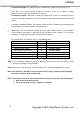
CPS600E Function description: The settings may be adjusted to the quality of the electricity in use. e. Slew Rate: Also called Dynamic Frequency Tolerance. There are 5 different settings (0.25,0.5,1,2,4 Hz/Sec). The default value is 4Hz/sec. Function description: “Slew Rate” indicates the tolerance of a device in accepting frequency variances. The lower “Slew Rate” results in less tolerance but better protection for the connected loads. f.
CPS600E FAULT WARNING DISPLAY AND ALARM 1. 2. 3. 4. 5. Overheat Protection: The EPS output will be interrupted. After 30 seconds, the machine shuts down and the LCD display output voltage is zero. Over-Load Protection: :The EPS output will be interrupted. After 30 seconds, the machine shuts down and Over Load Icon lights on the LCD display. Battery Missing: :You should hear a long beep and Battery Indicator flashes。 Low Battery Protection: The EPS output will be interrupted.
CPS600E TROUBLESHOOTING Problem Possible Cause Input fuse is blown due to overload. Outlet does not provide power to equipment. DC fuse is blown due to overload. Batteries are discharged. Unit has been damaged by a surge or spike. The EPS does not perform expected runtime. The EPS will not turn on. Batteries are not fully charged. Batteries are degraded. The on/off switch is designed to prevent the damage that rapidly turns it off and on. The unit is not connected to an AC outlet.
CPS600E TECHNICAL SPECIFICATIONS Model Capacity (VA) Capacity (Watts) Operation Technology CPS600E 600VA 420W AVR ( Single Boost & Single Buck ) AC Input Input Voltage Range Input Frequency Range AC Output Number of Phase On Battery Typical Output Voltage Nominal Output Voltage Configuration Note On Battery Output Frequency Overload Protection Transfer Time 170Vac – 270Vac 45~65Hz (auto sensing) Single Phase 0 ~40% LOAD Pure Sine Wave at 220Vac +/- 5% 40~100% LOAD Trapezoidal Wave at 220Vac+/- 5% Confi
CPS600E 13 Copyright © 2010 CyberPower Systems, Inc.
CPS600E Copyright © 2010 CyberPower Systems, Inc.
CPS600E For more information, contact us at: CyberPower Europe CyberPower Systems B.V. Flight Forum 3545, 5657DW Eindhoven, The Netherlands Tel: +31 (0)40 2348170 Fax: +31 (0)40 2340314 Website: http://eu.cyberpowersystems.com/ E-mail: sales@cyberpower-eu.com Entire contents copyright © 2010 CyberPower Systems, Inc. All rights reserved. Reproduction in whole or in part without permission is prohibited. 15 Copyright © 2010 CyberPower Systems, Inc.