
User`s manual
CPS600E
Copyright © 2010 CyberPower Systems, Inc.
5
BASIC OPERATION
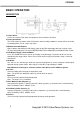
DESCRIPTION
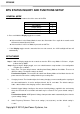
1. Power Switch
Used as the master on/off switch for equipment connected to the AC outlet.
2. Power On Indicator
This LED is above the power switch. It illuminates when the utility condition is normal and the AC outlet
is providing power, free of surges and spikes.
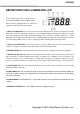
3. Multifunction LCD Readout
High resolution and intelligent LCD display shows all the EPS information with icons and messages.
For more information please check the DEFINITIONS FOR ILLUMINATED LCD INDICATORS section.
4. LCD Display Toggle / Selected Switch
Users can monitor EPS status and set up functions using the toggle. The buzzer on/off can also be
controlled by the toggle switch. Please refer to “EPS Status Inquiry and Functions Setup” section for
more details.
5. AC Outlet
The unit has one Schuko type outlet for connected equipment to ensure temporary uninterrupted
operation during a power failure. Max. Output is 6.3A; Max. Output wattage is 420W.
Note! Maximum cord length is 10 meters and the cable O.D. must be 14AWG or greater.
6. AC Inlet
Connect to utility power through the input power cord.
Note:The O.D. of the distribution cables must be 0.75mm or greater.
Input Fuse
The fuse provides optimal overload protection.
Note:The Input Fuse is 6.3A/250V.
7. Black Battery Cable (Negative (-))
Connect black (negative (-)) battery cable to the black (negative (-)) connector on the external battery.
Note: The Battery cable is 10AWG / 4 feet.
8. Red Battery Cable (Positive (+))
Connect red (positive (+)) battery cable to the red (positive (+)) connector on the external battery.
Note: The Battery cable is 10AWG / 4 feet.
9. DC Fuse
The fuse provides optimal overload protection for battery mode operation.