User’s Manual OL6KRT3UPM / OL6000RT3U OL8KRT3UPM / OL8000RT3U OL10KRT3UPM / OL10000RT3U CyberPower Systems Inc. www.cpsww.
IMPORTANT SAFETY INSTRUCTIONS This manual contains important instructions. Please read and follow all instructions carefully during installation and operation of the unit. Read this manual thoroughly before attempting to unpack, install, or operate the UPS. CAUTION! The UPS must be connected to a grounded AC power outlet with fuse or circuit breaker protection. DO NOT plug the UPS into an outlet that is not grounded. If you need to power-drain this equipment, turn off and unplug the unit.
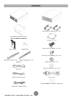
UNPACKING Power module Battery module Rackmount ears (Stands) (2) * 2 sets Input / Output terminal block cover (Only for OL8000RT3U/OL10000RT3U) Tie plate (1) * 1 set User’s manual Flat head screws: M5X8L (8) * 2 sets Register card Pan head screws: M5X12L (12) * 2 sets Rackmount left rail * 2 sets Rackmount right rail * 2 sets (Optional) Plastic washers (8) * 2 sets Phone line Screw hole dust covers (10) * 2 sets USB communication cable Power cords PowerPanel® Business Edition software CD S
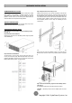
HARDWARE INSTALLATION HARDWARE INSTALLATION Step 4: Adjust rackmount rails to fit your rack These versatile UPS systems can be mounted in a rackmount or vertical tower orientation. This versatility is especially important to growing organizations with changing needs that value having the option to position a UPS on a floor or in a rackmount system. Please follow the instructions below for the respective mounting methods.
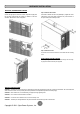
HARDWARE INSTALLATION VERTICAL/TOWER INSTALLATION Step 1: Rotate the Multifunction LCD Module Step 2: Attach the base stands Unscrew the right panel of the Power module. Separate the right panel from the UPS. Gently lift the LCD module out. Rotate it to the tower orientation. Reinstall it for a tower configuration. Secure the tie bracket with the screws (M5X8*4pcs). Tighten the screws (M5X12*4pcs) of the base stands (rackmount ears) onto the bottom of the power module and the battery module.
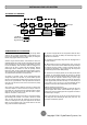
INSTALLING YOUR UPS SYSTEM SYSTEM BLOCK DIAGRAM Bypass Input Input Filter PFC AC/DC Charger AC/DC Battery Inverter DC/AC BUS STS Control & Monitoring Output Filter Output LCD Module USB & DB9 SNMP Slot Line Mode Battery Mode Bypass Mode HARDWARE INSTALLATION GUIDE 1. Battery charge loss may occur during shipping and storage. Before 6. This UPS is equipped with an auto-charge feature.
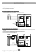
HARDWIRING THE INPUT/ OUTPUT TERMINALS CHECK CIRCUIT BREAKER/WIRING Check branch circuit breaker rating and wiring dimensions with the following table. UPS Capacity Branch Circuit Breaker Wiring AWG Wiring mm 6KVA 40A 10 AWG 5.5 mm 2 8KVA 50A 8 AWG 8.0 mm 2 10KVA 60A 6 AWG 14.0 mm 2 2 INPUT/ OUTPUT CONFIGURATION Hardwire the input/output terminals as shown in the following diagram.
HARDWIRING THE INPUT/ OUTPUT TERMINALS Step 3: Input configuration Insert the input cable through the appropriate cable gland (not included). Step 4: Output configuration Insert the output cable through the appropriate cable gland (not included) Connect the three wires to the output terminal block. Connect the three wires to the input terminal block. Step 5: Fix the top cover on the bottom cover Tighten the six screws to fix the top cover on the bottom cover. 7 Copyright © 2011 CyberPower Systems, Inc.
BACKFEED PROTECTION BACKFEED PROTECTION OPERATION 1. If the Bypass circuit is shorted and the UPS is running in Line Mode or Battery Mode, backfeed protection will be active and the external isolation device (Magnetic Contactor) will open. 2. Save your data and perform a controlled shutdown. 3. Contact CyberPower for repair. WITHOUT BACKFEED PROTECTION CONFIGURATION 1. Hardwire the input terminals as shown in the following diagram. 2.
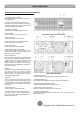
BASIC OPERATION POWER MODULE FRONT/REAR PANEL DESCRIPTION 1. Power Button / Power on Indicator Master ON/OFF for the UPS. Indicates that the UPS is on and supplying power. 2. UPS Status / Fault / Replace Battery LED Indicator Indicates the status of the UPS whether is operating in Line, Battery or Bypass Mode, or the UPS has an internal fault and the battery need to be replaced. 3. Multifunction LCD Readout Shows UPS status, information, settings and events. 4.
BASIC OPERATION BATTERY MODULE FRONT/REAR PANEL DESCRIPTION 1. On-board Replaceable Fuse Cover Replaceable fuse is accessible from the rear panel. It must be done by qualified personnel. 2. AC Circuit Breaker Provides overload and fault protection. 3. AC Output Outlet Use this outlet to connect to the AC Input Inlet of a downstream Battery module. 4. AC Input Inlet (Charge Only) AC power connectivity to wall receptacle. 5. Input Connector Use this input connector to daisy chain the next Battery module.
BASIC OPERATION CONNECTION #2 : POWER MODULE WITH MULTIPLE BATTERY MODULES Step 1: Connect the 1st Battery module to the Power module using the instructions above. Step 2: Turn off the DC breaker of the 2nd Battery module. Step 3: Loosen the two screws to remove the battery cable retention bracket of the 1st battery module. Step 4: Use the output cable of the 2nd Battery module to connect the 2nd Battery module to the 1st Battery module.
OPERATION INSTRUCTIONS FOR LCD MODULE LED INDICATORS – UPS STATUS LED Indicators Color UPS Status Description ON/OFF White UPS power is on. ON-LINE Green UPS is operating in Line Mode. BATTERY ON Yellow UPS is operating in Battery Mode. BYPASS Yellow UPS is operating in Bypass Mode, Manual Bypass or ECO (Economy) Mode. FAULT Red UPS has an internal fault. See “Trouble Shooting” for additional information.
LCD SETUP FUNCTIONS MULTI-FUNCTION LCD MAIN MENU Press “Enter” button to activate “MAIN MENU”. MAIN MENU submenu Function Description Information Displays the UPS information. Configure Displays the UPS settings that can be configured by the user. Event Log Displays the 3 most recent events, (day/hour/minute), and event description. by event count, time LCD INFORMATION READOUT There are 19 types of UPS information available for display. 1. Press the “ENTER” button to activate the “MAIN MENU”.
LCD SETUP FUNCTIONS LCD EVENT LOG 3 Event Logs of UPS can be recorded. 1. Press the “ENTER” button to activate the “MAIN MENU”. 2. Press the “▲” and “▼” buttons to scroll to the “Event Log” option. 3. Press the “ENTER” button to select the “Event Log” submenu. 4. Press the “▲” and “▼” buttons to scroll through the “Event Log” submenu in the following table. 5. Press the “ESC” button to return to UPS Status.
LCD SETUP FUNCTIONS Configure Submenu Available Settings Default Setting Output Voltage* = [200V] [208V] [220V] [230V] [240V] 220V Range= [+/- 1%] [+/- 2%] [+/- 3%] [+/- 4%] [+/- 5%] Sync Freq Window +/- 5% [+/- 6%] [+/- 7%] [+/- 8%] [+/- 9%] [+/-10%] Range= [+10%/-10%] [+10%/-15%] [+10%/-20%] Bypass V Window Bypass Condition +10%/-15% [+15%/-10%] [+15%/-15%] [+15%/-20%] [Check Freq/Volt] [Check Volt Only] [No Bypass] Check Freq/Volt [Disable] [Enable] Disable ECO Mode** [V Range= +/-15%] [V R
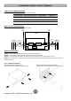
LCD MODULE REMOTE CONTROL and WALL-MOUNTING INSTRUCTIONS REMOTE CONTROL WALL-MOUNTING INSTRUCTIONS Step 1: Remove the Multifunction LCD Module Step 1: Remove the Multifunction LCD Module Unscrew the right panel of the Power module. Separate the right panel from the UPS. Gently lift the LCD module out. Reinstall the right panel. Unscrew the right panel of the Power module. Separate the right panel from the UPS. Gently lift the LCD module out. Reinstall the right panel.
MAINTENANCE CAUTION! Do not open or mutilate the batteries. Electrolyte fluid is harmful to the skin/eyes and may be toxic. CAUTION! To avoid electric shock, turn off and unplug the UPS from the wall receptacle before servicing the battery. CAUTION! Only use tools with insulated handles. Do not lay tools or metal parts on top of the UPS or battery terminals. Storage To store your UPS for an extended period, cover it and store with the battery fully charged.
TECHNICAL SPECIFICATIONS Model Configuration Capacity (VA) Capacity (Watts) Form Factor Energy-saving Technology Input Input Voltage Range Input Frequency Range Input Power Factor Cold Start Output Output Waveform Output Voltage* Output Frequency Transfer Time (Typically) Rated Power Factor Harmonic Distortion Crest Factor ECO Mode Voltage Regulation UPS Outlets Protection Surge Protection Phone / Network Protection Overload Protection Short Circuit Protection Battery Specifications Recharge Time (Typically
CONFORMANCE APPROVALS Problem Warning O/P Overload Load Over XXX% Battery Mode Possible Cause Solution Your equipment requires more power than the UPS can provide. If the UPS is in Line Mode then it will transfer to Bypass Mode; if the UPS is in Battery Mode it will shutdown. Your equipment requires more power than the setting in the Power Management Software ® (PowerPanel Business) will allow. BAT Disconnected Battery Failure UPS has failed in Battery Test.