OL1000RMXL2U OL1500RMXL2U OL2000RMXL2U OL3000RMXL2U Paragon Series User Manual
Preface About this Manual Thank you for purchasing a CyberPower Systems product to protect your electrical equipment. The Paragon series has been designed with the utmost care. We recommend that you take the time to read this manual to take full advantage of your UPS’s many features. The Paragon UPS and the optional battery packs that are covered in this manual are listed below: - UPS OL1000RMXL2U (1000VA/700W). - UPS OL1500RMXL2U (1500VA/1050W). UPS OL2000RMXL2U (2000VA/1400W).
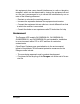
this equipment does cause harmful interference to radio or television reception, which can be determined by turning the equipment off and on, the user is encouraged to try to correct the interference by one or more of the following measures: • Reorient or relocate the receiving antenna • Increase the separation between the equipment and receiver • Connect the equipment into an outlet on a circuit different from that to which the receiver is connected • Consult the dealer or an experience radio/TV technician
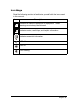
Icon Usage Read the following section to familiarize yourself with the icons used in this manual: Icon Description Indicates a hazard to personnel or equipment. These warnings must always be followed. Indicates notes, useful tips, and helpful information. Indicates essential information. LED off. LED on. LED flashing.
Safety Instructions Read before installing SAVE THESE INSTRUCTIONS. This manual contains important instructions that should be followed during installation, operation, and maintenance of the UPS and batteries. CAUTION: Personal Safety ❑ The UPS has its own internal power source (the battery). Consequently, the power outlets may be energized even if the UPS is disconnected from the AC power source. ❑ Dangerous voltage levels are present within the UPS.
CAUTION: Product Safety ❑ ❑ ❑ ❑ ❑ ❑ ❑ ❑ ❑ The UPS connection instructions and operation described in the manual must be followed in the order indicated. The UPS must be connected to a nearby wall outlet that is easily accessible. The UPS can be disconnected from the AC power source by removing the power cord. Ensure that the electrical specifications on the rating plate for your AC powered system and the actual electrical consumption of all the equipment to be connected to the UPS are compatible.
Contents Preface .............................................................................i Safety Instructions ............................................................. iv Device Overview .............................................................…..1 System configurations ............................................................... ..1 Rear panel ..............................................................................… 2 Control panel ..................................................
1 Device Overview 1.1 System configurations Rack setup Model Dimensions (WxDxH)(inch) Weight (pound) OL1000RMXL2U 17.24x18.66x3.41 43 OL1500RMXL2U 17.24x18.66x3.41 45.19 OL2000RMXL2U 17.24x25.69x3.41 70.11 OL3000RMXL2U 17.24x25.69x3.41 72.
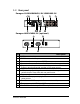
1.2 Rear panel Paragon OL1000RMXL2U/OL1500RMXL2U 1 3 4 6 2 8 9 6 7 5 8 10 11 9 Paragon ABP36VRM-2U (optional) 4 8 NO 1 2 3 4 5 6 7 8 9 10 11 12 12 8 Description USB communication port. RS232 communication port. Connector for remote power off (RPO). Connector for automatic detection of an additional battery pack. Expansion slot for optional communication card. Button to test phase/neutral inversion of AC power source.
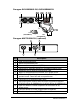
Paragon OL2000RMXL2U/OL3000RMXL2U 8 8 1 7 7 4 6 10 11 5 3 2 3 L5-20R/ L5-30R L5-30P 5-20P (OL3000RMXL2U) (OL2000RMXL2U) 9 Paragon ABP72VRM-2U (optional) 4 8 NO 1 2 3 4 5 6 7 8 9 10 11 12 12 8 Description USB communication port. RS232 communication port. Connector for remote power off (RPO). Connector for automatic detection of an additional battery pack. Expansion slot for optional communication card. Button to test phase/neutral inversion of AC power source.
The compatibility of optional battery packs: ABP36VRM-2U is for OL1000RMXL2U and OL1500RMXL2U UPS units. ABP72VRM-2U is for OL2000RMXL2U and OL3000RMXL2U UPS units. Refer to the tables in this chapter for all illustration numbering throughout this manual (unless specified otherwise).
1.3 Control panel 13 NO 14 15 16 17 18 19 20 21 22 23 24 Description 13 14 15 16 17 18 ON / OFF. BATT: Operation on battery power. INV: Operation in ON-LINE mode (backup power available). BYPASS: Operation on bypass (no backup power available). OUTLET 2: Status of programmable outlet 2. OUTLET 1: Status of programmable outlet 1. : LED on indicates the outlet is supplied with power. : LED flashing indicates the outlet status change in progress. 19 ➣ ➣ BZ STOP (TEST): Lamp test or buzzer OFF.
2 Installation 2.1 Unpacking The following items are included in the box along with the UPS.
2.2 Installing the UPS in a rack Follow the steps below to rack mount the UPS on the rails. The telescopic rails and mounting hardware for rack mounting the UPS have been supplied. 3 1 3 7 2 6 4&5 2 7 A. B. C. D. 4 5 Secure rails together with three screws (1). Attach front rails to rack front (2). Attach rear rails to rack rear (3). Attach both front brackets (4&5) to each side of UPS and slide UPS into the rack (6). Do not lean or place objects on top of unit at any time.
2.3 Setting the UPS in the vertical position Attach the two tower supports to the UPS as shown below. Pull out the CyberPower Logo plate, rotate it as shown, and replace it in the front of UPS.
2.4 Connecting the RS232 or the USB communication port (optional) Connect the UPS to a PC using the RS232 or USB communication port as shown below. 1 2 OL1000RMXL2U/OL1500RMXL2U UPS shown. 1. Connect the RS232 or the USB communication cable to the corresponding port on the computer. 2. Connect the other end of the communication cable to the either the RS232 1 or USB 2 communication port on the UPS. The RS232 and USB communication ports cannot be used at the same time.
2.5 Installing the optional communication card 5 OL1000RMXL2U/OL1500RMXL2U UPS shown. It is not necessary to shut down the UPS to install the communication card: 1. Remove the slot 5 cover secured by two screws. 2. 3. Insert the card in the slot. Secure the card with the two screws. 2.6 Connections Check that the rating indicated on the back of the UPS corresponds to your AC-power system and to the actual electrical consumption of all the equipment to be connected to the UPS.
OL2000RMXL2U/OL3000RMXL2U UPS 5-15P or 5-20P 5-20P(OL2000RMXL2U) Input cable A L5-30P(OL3000RMXL2U) Input cable 1. 2. L5-20R/L5-30R(Receptacle) Output cable Connect the input power cord (A) to the AC-power wall receptacle. Connect the protected equipment to the UPS. It is advisable to connect priority loads to the NEMA 5-15/20P outlets (B) and/or power cord (D) and any non-priority loads to the two programmable outlets (C).
3 Operation 3.1 Start-up The protected equipment connected to the UPS can be powered up, whether AC input power is available or not. 13 14 15 16 17 18 19 20 21 22 23 24 The AC input power source must be present when powered by the UPS for the first time. Press the ON / OFF button. The UPS will boot in one of the following conditions: • The buzzer sounds and all the LEDs light up.
3.2 LED indicators LEDs 21 to 1. 24 provide three different indications: Remaining backup time as a percentage (during normal operation). 2. Percentage of load drawn by the protected equipment, when button 20 is pressed. 3.
3.3 Operation on battery power (following AC input power failure) Transfer to battery power 14 The AC power source is out of tolerance, LED buzzer sounds three times. 14 is ON, the The AC power to equipment connected to the UPS is supplied by the battery. Threshold for the low-battery warning 14 The low-battery warning threshold can be set by the user, with the PowerPanel Business Edition Agent software (see Personalization (option) on page 15). LED 14 flashes. The buzzer sounds every three seconds.
End of backup time 19 The buzzer sounds continuously. Press button OFF. 19 to turn the buzzer The equipment is no longer supplied with power. The UPS goes into sleep mode at the end of the battery backup time, until complete shutdown. Make sure that the automatic-restart function has been enabled (Personalization (option) on page 15) for the return of AC input power. 3.
PowerPanel Business Edition Agent installation: 1. Insert the provided CD containing the PowerPanel Business Edition Agent software into the computer’s CD ROM drive. 2. The installation software should load automatically. If not, open the file manager and select the CD-ROM drive. 3. Launch "software\setup.exe". 4. Follow the instructions to install the software. You can download the PowerPanel Business Edition Agent software from the CyberPower Systems web site at www.cyberpowersystems.
Allow to bypass even if utility power is out of range. Options: Enabled / Disabled Default: Disabled Battery Backup supplies power at the specified voltage. Options: 110 / 120 / 127 Default: 120 Output Frequency Determination - Following utility frequency when it is within the specified tolerance. (default) [When checked, the value can be modified from the drop-down box.] Options: 1~10% Default: 5% - Fixed on the specified frequency. [When checked, the value can be modified from the drop-down box.
Battery Prohibit battery from discharging over 4 hours. Options: Enabled / Disabled Default: Disabled Battery Backup will shut down to save energy if power failed without any load after 5 minutes. Options: Enabled / Disabled Default: Disabled Perform a battery test once during the specified period. Options: every week / every month Default: every week The latest battery replaced date.
3.5 UPS Shutdown 13 Press button 13 to turn off the UPS. The connected equipment is no longer supplied with power. 3.6 UPS Remote Power Off The Paragon UPS is equipped with a Remote Power Off function (RPO) that can cut power from all the devices connected to the UPS using a remote-operated contact. The function is implemented by opening a contact connected to the two terminals of connector 3 on the back of the UPS. 3 BA OL1000RMXL2U/OL1500RMXL2U UPS shown.
Installation and test of the remote power off function 1. Check that the UPS is shut off and disconnected from the AC power source. 2. Remove the RPO connector 3 by undoing the screws (A). 3. Connect an insulated dry contact (NC, 60V DC, 30V AC max., 20mA max., cable size 0.75mm) to the two terminals of the RPO connector (B). 4. Put the RPO connector 3 back in place on the back of the UPS. 5. Connect the UPS to the AC-power source and restart it as indicated previously. 6. 7.
4 Maintenance 4.1 Troubleshooting If any of LEDs ○22 ○23 or 24 flash, there is an alarm or an abnormal operation. See the table below for problems and solution. If an LED flashes, the bargraph data is no longer displayed. Indication LED Signification UPS overload. Overload is too long or too high. - If AC power is present and within tolerance, the UPS changes to bypass mode (supplied directly by the AC outlet). LED 16 flashes. The buzzer sounds every second.
Indication Signification The yellow LED 21 flashes, the red indicator light 7 behind the UPS comes on and the buzzer sounds continuously. The phase and neutral positions of your electrical network are showing reversed positions. Directly grounded neutral type networks: Check the cabling of phase and neutral on your electrical network.
4.2 Replacement of the battery module Load will not be protected during this procedure! Batteries constitute a danger (electrical shock, burns). The short-circuit current may be very high. Precautions must be taken when handling. Safety Rules: Remove all watches, rings, bracelets and any other metal objects that may come into contact with the battery modules. Use tools with insulated handles. Removal of the battery modules A : Unclip the small plate with the CyberPower Systems logo on the UPS front panel.
C : Remove the left part of the front panel. D : Remove the screw and cover plate. E : Disconnect the connectors. F : Remove the battery modules. E D C F Reinstallation of the battery modules To reinstall the battery modules, perform this procedure in reverse order. To maintain an identical level of performance and safety, use battery modules identical to those previously mounted in the UPS. Press the two parts of the battery connector tightly together to ensure proper connection.
5 Appendix 5.1 Technical Characteristics SAFETY RELAY AC INPUT AC/DC PFC CONVERTER EMI FILTER BATTERY POWER CHARGER SUPPLY DC/AC INVERTER BYPASS RELAY EMI FILTER AC OUTPUT DC/DC PUSH PULL BATTERY 5.
Load Crest Factor Ratio Frequency Regulation 3:1 (50Hz / 60Hz) ± 0.5% (Battery mode) Efficiency OL1000RMXL2U/OL1500RMXL2U: >87% @100% R Load; >86% @100% RCD Load OL2000RMXL2U: >86% @100% R Load; >84% @100% RCD Load OL3000RMXL2U: >88% @100% R Load; >86% @100% RCD Load Over Load Capacity 100% < Load < 110% overload warning only; 110% < Load < 130% warning, transfer to bypass after 12 seconds; 130%≤ load warning, transfer to bypass after 1.
Communications RS-232/USB AS400 AS 400 Card (Optional) Remote Capability HTTP/SNMP Card (Optional) Emergency Power Off (EPO) Yes Agency Safety UL1778/cUL CSA22.
Battery Pack Model Compatible ABP36VRM-2U OL1000RMXL2U/ OL1500RMXL2U Battery Voltage Voltage x Rating x Quantity 36V 12V x 7 AH x 6 (2 Strings of 3 ABP72VRM-2U OL2000RMXL2U/ OL3000RMXL2U 72V 12V x 9 AH x 1 2 (2 Strings of 6 in Serial) in Serial) >20 Minutes Unit + 1 Battery Pack >40 Minutes Unit + 2 Battery Pack >60 Minutes Unit + 3 Battery Pack >80 Minutes Unit + 4 Battery Pack Long Backup Time (External Battery Pack) Dimensions (W x D x H ) (inch) Weight (pound) 28 Appendix 17.24x18.66x3.
Limited Warranty and Connected Equipment Guarantee In purchasing a OL1000RMXL2U/OL1500RMXL2U/OL2000RMXL2U/OL3000RMXL2U in the United States or Canada, the original end user receives a Limited Warranty and Connected Equipment Guarantee from Cyber Power Systems (USA), Inc. (for ease of reading, referred to as "CyberPower"). The Limited Warranty and the Connected Equipment Guarantee are intended to be the original end-user's exclusive rights and remedies.
LIMITED WARRANTY CyberPower warrants to you, the Initial Purchaser, that the Product will be free from defects in material and workmanship for three years from the date of original purchase, subject to the terms of this Limited Warranty. Any Implied Warranty of Merchantability or for Fitness for a Particular Purpose, if applicable to the Product, is limited in duration to the period of ownership by the Initial Customer.
the full purchase price you paid for the Product (purchase receipt showing price paid is required). CONNECTED EQUIPMENT GUARANTEE If you are the Initial Purchaser and the Product is still covered by the Limited Warranty, the Connected Equipment Guarantee provides protection for damage to equipment connected to the Product ("Connected Equipment"), subject to certain terms and limitations. The Connected Equipment Guarantee is not "first dollar" coverage. It is secondary.
1 Complete and return the CyberPower Warranty card or provide reasonable proof of purchase, for example, a sales receipt that establishes you as the original end-user consumer purchaser of the Product. 2 Call CyberPower at (952) 403-9500 or (877) 297-6937 (toll free), write to CyberPower at 5555 12th Ave East, Suite 110, Shakopee, MN 55379, or e-mail CyberPower at claims@cyberpowersystems.com within ten (10) days of the date of the event for which you wish to make a claim for warranty service.
If CyberPower replaces the connected equipment or pays to the Initial Customer the Agreed Damage Amount, the Initial Customer shall transfer ownership of all item(s) to CyberPower without warranty by the Initial Customer, but free of lien or other interest. CONDITIONS COMMON TO THE LIMITED WARRANTY AND THE CONNECTED EQUIPMENT GUARANTEE The Limited Warranty and the Connected Equipment Guarantee are the only and the exclusive express warranty of CyberPower with respect to the Product.
CyberPower Does Not Cover or Undertake Any Liability in Any Event for Any of the Following: 1 Loss of or damage to data, records, or software or the restoration of data or records, or the reinstallation of software.
ANY SUCH USE IS IMPROPER AND IS A MISUSE OF A CYBERPOWER PRODUCTS. The Limited Warranty and the Connected Equipment Guarantee are governed by the laws of the United States and the State of Minnesota, without reference to conflict of law principles. The application of the United Nations Convention of Contracts for the International Sale of Goods is expressly excluded.