
User Manual

Copyright © 2018 Cyber Power Systems, Inc.
8
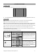
1. GENERAL MODE
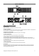
a. Press the Display toggle button to check the status of the UPS status:
#
Items
Unit
1
Input Voltage
V
2
Output Voltage
V
3
Output Frequency
Hz
4
Load
Kw
5
Load Capacity
%
6
Battery Capacity
%
7
Estimated Runtime
Min
b. If the LCD backlight turns off (enters sleeping mode), press the Display toggle button to wake it up.
2. SET-UP MODE
Step 1: Press and hold the Display toggle button for 3 seconds to enter the UPS Set-Up Mode.
Step 2: By pressing the Display toggle, users can switch between setup functions.
Step 3: Press and hold the Display toggle button for 3 seconds to choose the function you want to adjust.
When the icons blink, the value of each item is changed by slightly pressing the Display toggle button.
Note: If the function you select is ESC, the UPS will return to Function Menu (Step 2) without any change.
Step 4: To save the value and return to Function Menu, press and hold the toggle for 3 seconds.
Note: If the Display button is not touched for 30 seconds, the UPS will leave Set-up Mode and return to
General Mode without changing any settings.
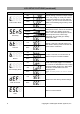
Programmable functions are sorted as the following table:
Functions
Options
Description
Output Quality
Low
Low Output Quality means UPS will go to
battery mode less often and tolerate more
utility power fluctuations and vice versa.
Note: It is related to the settings of
High/Low Transfer Point. The LCD shows
“CUSt”, instead of “LInE”, with capacity bar
when High/Low Transfer Point is modified.
Medium
High
ESC
Customized
High Transfer Point
136V
It is the setting of maximum output
voltage. If the utility voltage is usually high
and the connected equipment can work
with this condition, you can set High
Transfer Point higher to avoid UPS going
to battery mode too often.
139V
142V
ESC
LCD SETUP FUCTIONS