
User Manual


3 Copyright © 2016 CyberPower Systems, Inc.
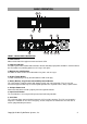
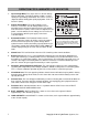
5. Press the power switch to turn the UPS on. The Power-On indicator light will illuminate. If an overload
is detected, an audible alarm will sound and the UPS will emit one long beep. In order to reset it, turn
the unit off and unplug some equipment from outlets. Make sure the total load of the equipment
connected to the UPS is within the unit’s safe range, (refer to the technical specifications), and then
turn the unit on.
6. To maintain an optimal battery charge, leave the UPS plugged into an AC outlet at all times.
7. Before storing the UPS for an extended period of time, turn the unit OFF. Then cover it and store it
with the batteries fully charged. Recharge the batteries every three months or so, to ensure good
battery capacity and long battery life; further, this might also prevent damage to the unit from an
unlikely battery leakage.
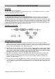
8. The unit provides one Serial port and one USB port to allow connection and communication between
the unit and any attached computers. The Serial Port as well as its paired USB port allow for
bi-directional communication among the UPS and the primary connected computer running the
PowerPanel
®
Business Edition Software. The computer can monitor the UPS and alter its various
programmable parameters. When there is a power failure, the computer connected to the port will
start to shut down after a user controlled delay based on the settings given to the PowerPanel®
Business Edition Software.
Note: If the USB port is used, the serial port will be disabled. They cannot be used simultaneously.
Note: PowerPanel® Business Edition Software is available on our website. Please visit
www.cyberpowersystems.com and go to Products/Software page for free download.
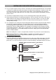
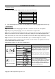
9. EPO (Emergency Power Off) Port:
Follow the appropriate circuit diagram below to wire the cable to your EPO configuration. The EPO
remote switch is a switch installed in an outside area, connected to the unit via an ordinary RJ-11
phone line. In case of an emergency, it can be used to immediately cut-off power from the UPS unit.
RJ11
PLUG
1
2
3
4
3-4 JUMPER
N.C.EPO SWITCH
OPTION 2: USER SUPPLIED NORMALLY CLOSED SWITCH
RJ11
PLUG
1
2
3
4
NO CONNECTION
N.O.EPO SWITCH
OPTION 1: USER SUPPLIED NORMALLY OPEN SWITCH
(RECOMMENDED)
NO CONNECTION
INSTALLING YOUR UPS SYSTEM
(continued)