User Manual Automatic Transfer Switch
Table of Contents Overview.................................................................................................... 1 Model List.................................................................................................. 1 Product Contents............................................................................... 2 For 1U Series............................................................................................ 2 For 2U Series.....................................................
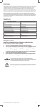
Overview CyberPower Automatic Transfer Switches equip with dual sources that can provide redundant and more reliable power to critical devices with single input. Users can define Source A or B as preferred power supply. When selected source is unstable or unavailable, ATS will switch to another source to constantly provide power to connected devices. The entire ATS series are designed with LED plus LCD interfaces so that users can easily observe power status and device load.
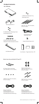
Product Contents For 1U Series 2 (M3x4) Cord Retention Tray Mounting Screws ATS Mounting Bracket x 2 Cable Ties: Qty. 18 for 10 outlets, 21 for 12 outlets 24 (M4x8) Bracket Mounting Screws (Include eight spares) RJ45/DB9 Serial Port Connection Cable 6 (M5x12) Rack Mounting Screws/ 6 Washers (Include two spares for each) Jumper (Switched type only) Cybe rPow er Reliab R ility. Qualit y. Value.
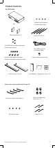
Product Contents For 2U Series 4 (M3x4) Cord Retention Tray Mounting Screws ATS Mounting Bracket x 2 Cable Ties: Qty. 30 24 (M4x8) Bracket Mounting Screws (Include eight spares) RJ45/DB9 Serial Port Connection Cable Jumper (Switched type only) 6 (M5x12) Rack Mounting Screws/ 6 Washers (Include two spares for each) Cybe rPow er Reliab R ility. Qualit y. Value.
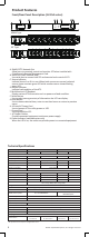
Product Features Front/Rear Panel Description (1U 15A series) A B C D E F G Source Output - Normal - Warning - Overload B Serial Port Enter PDU20SWHVIEC10ATNET QCN-0000003-00 NEMA Type Source A Select A Expansion Port Provides SNMP Card Communication J Source B 100-120V 50/60 Hz 1 H 2 3 4 5 I IEC Type 9 10 3 4 5 6 7 8 9 10 11 12 K Source B A. SNMP/HTTP Network Slot Allow users to remotely control and monitor ATS when installed with CyberPower’s Remote Management Card.
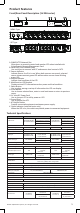
Product Features Front/Rear Panel Description (1U 20A series) A B C D E F G Source Output - Normal - Warning - Overload B Serial Port Enter PDU20SWT10ATNET QCN-0000002-00 NEMA Type Source A Select A Expansion Port Provides SNMP Card Communication J Source B 100-120V 50/60 Hz 1 H 2 3 4 6 7 8 9 10 K IEC Type Source B J 200-240V 50/60 Hz Source A 5 I 1 H 2 3 4 5 6 I 7 8 9 10 K A.
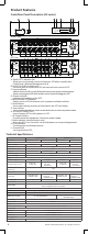
Product Features Front/Rear Panel Description (2U series) A C B D E F G Source Output A Select B1 - Normal - Warning - Overload B2 Expansion Port B Provides SNMP Card Communication B3 Enter PDU30SWT17ATNET QCN-0000005-00 Serial Port NEMA Type I Source A Bank1 , 20A Bank3 , 24A Source B 100-120V 50/60 Hz 1 2 3 4 5 6 7 8 L5-30R Bank2 , 20A 17 9 10 11 12 H 13 14 15 16 K J IEC Type L I Source A Bank1 , 20A Bank3 , 24A Source B 200-240V 50/60 Hz 1 2 3 4 5 6
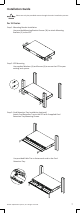
Installation Guide Please use only the provided screws through the entire installation process. For 1U Series Step 1. Mounting Bracket Installation Use provided Mounting Bracket Screws (16) to attach Mounting Brackets (2) to the ATS. Step 2. ATS Mounting Use supplied Washers (4) and Screws (4) to secure the ATS to your existing rack system. Step 3: Cord Retention Tray Installation (optional) Attach Cord Retention Tray to the ATS with 4 supplied Cord Retention Tray Mounting Screws.
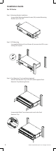
Installation Guide For 2U Series Step 1. Mounting Bracket Installation Use provided Mounting Bracket Screws (16) to attach Mounting Brackets (2) to the ATS. Step 2. ATS Mounting Use supplied Washers (4) and Screws (4) to secure the ATS to your existing rack system. Step 3. Cord Retention Tray Installation (optional) Attach Cord Retention Tray to the ATS with 8 supplied Cord Retention Tray Mounting Screws. Use provided Cable Ties to fasten each cord to the Cord Retention Tray. 8 ©2014.
Installation Guide Replace LCD Panel Step 1. Use slotted screwdriver to gently lift out the LCD panel. Step 2. Disconnect cable connectors. Electrical Installation Step 1. Receptacle evaluation Ensure that the plug type of your ATS unit matches the wall receptacle type that you are using. The ATS must be plugged into a three-wire, grounded wall receptacle only. The wall receptacle must also be connected to an appropriate branch circuit/main with fuse or circuit breaker protection.
Installation Guide Network Installation (performed when Remote Management Card is available) Step 1. Attach the LAN Cable Use a CAT5 RJ45 cable, attach one end to the Ethernet port on the RMCard, and the other end to a network port. Step 2. Establish the ATS IP address Assigning an IP address to the CyberPower ATS requires the user to have an available IP address that is valid on the respective network. If an available IP address is unknown, contact the network administrator to obtain one.
Installation Guide Power Cord Retention Clip Installation- For IEC type ATS Input Power Cord Retention Cable Clip Installation Step 1. Remove screw next to the inlet. Step 2. Attach Cable Tie on the ATS and secure it with removed screw in the previous step. Step 3. Place a Power Cord Retention Cable Clip on the power cord. Align and insert the Cable Tie into the Cable Clip as shown in the figure below. Step 4.
Installation Guide Power Cord Retention Clip Installation Step 1. Remove screws next to the outlet where IEC Socket Power Cord Stand will be installed. Step 2. Attach IEC Socket Power Cord Stand on the ATS and secure it with removed screws in the previous step. Step 3. Attach Cable Tie on the IEC Socket Power Cord Stand and secure it with provided screw. Step 4. Place a Power Cord Retention Cable Clip on the power cord. Align and Insert the Cable Tie into the Cable Clip as shown in the figure below.
Installation Guide Remove the Power Cord Retention Clip Step 1. To remove the Power Cord Retention Clip by pushing it to the right as shown in the figure below. Step 2. Remove the Power Cord Retention Clip by pulling the clip (show in the image below) to the left. Operation Remote Management The remote management function provides for monitoring the ATS vitals, controlling outlets and utilizing SNMP functionality. Web Remote management can be performed via web interface.
Operation Local Management LCD Operation The LCD display provides ATS’s instant information, such as Source condition, Voltage, Current and so on. In addition, users can use the interface to configure each parameter and control each outlet of the ATS. A. Scroll Mode: The ATS information will display in following order automatically when “Scroll Mode On” is configured.
Operation Device Reset ● To reset all the settings to default locally, use Reset item in the LCD display. ● To reset all the settings to default remotely, log in Web interface, enter Reset page and apply the function. Unattended/Automatic Shutdown PowerPanel Business Edition software automatically intitiates a graceful shutdown on the operating system in an orderly fashion. PowerPanel must be installed on every PC for which the shut down is to take place.
Operation 4. ATS will reboot and show main menu on Hyperterminal. 5. Press “1” to select ATS upgrade 6. Select Transfer > Send File 7. Note that the Ymodem protocol and file “C:\cpsatsmafw_xxx.bin” are selected in Hyperterminal 8. Download progress window will open after click Send button 9. After upload binary file Hyperterminal will show as below 16 ©2014. CyberPower Systems, Inc. All rights reserved.
Operation 10. Use the command “@NEW” 11. ATS will reboot and show main menu on Hyperterminal 12. Press “2” to select LCD upgrade 13. Press “1” 14. Select Transfer > Send File 15. Note that the Ymodem protocol and file “C:\cpsatslafw_xxx.bin” are selected in Hyperterminal ©2014. CyberPower Systems, Inc. All rights reserved.
Operation 16. Download progress window will open after click Send button 17. After upload binary file Hyperterminal will show as below You can check to see if the firmware upgrade is successful by checking the “CyberPower System Firmware Version” after login. Note : 1. Please do not turn the ATS off and ensure the quality of selected source when processing firmware upgrade. Source will not perform switch function when upgrading firmware. 2. Press “3” to exit the main menu of firmware upgrade.
Operation 7. The system will reboot after you type “quit”. This reboot will take approx. 30 seconds 8. Login to the FTP again - ftp - ftp> open - To [current IP of the RMCARD] [port] (for example: To 192.168.22.126 21) [21 is the default ftp port for theRMCARD]) - Input USER NAME and PASSWORD 9. Upload cpssnmpdata _XXX.bin - ftp > bin - ftp > put cpssnmpdata _XXX.bin 10. Upgrade complete , type - ftp > quit 11.
Customer Service & Warranty Product Registration Thank you for purchasing a CyberPower product. Prompt product registration entitles coverage under the Limited Warranty and also allows the opportunity to be notified of product enhancements, upgrades, and other announcements. Registration is quick and easy at www.CPSww.com under “Support”. CyberPower International Feel free to contact our Tech Support department with installation, troubleshooting, or general product questions. CyberPower Systems, Inc.
Customer Service & Warranty Who Pays for Shipping? We pay when we send items to you; you pay when you send items to us. What Are Some Things This Warranty Does Not Cover? 1. This Warranty does not cover any software that is damaged or needs to be replaced due to the failure of the Product or any data that is lost as a result of the failure or the restoration of data or records, or the reinstallation of software. 2.
Appendix A-Hyper Terminal Hyper Terminal software can be used for basic ATS configuration. It utilizes a textbased interface and menu system. Navigation through the interface is done by typing the number of the menu option and pressing the Enter key. Note: The session will timeout and logout after 3 minutes of inactivity. Menu options are shown below: [Main Menu] 1. Utility Configuration 2. Outlet Manager (Switched Series Only) 3. Load Configuration 4. Network Settings 5. System Configuration 6.
Appendix B-Power Device Network Utility Overview The CyberPower Power Device Network Utility is an easy-to-use interface which is used for establishing IP addresses on CyberPower ATS devices. Installation Step 1. Insert the CD labeled “Software Installation CD” into the CD/DVD drive. Step 2.Select Power Device Network Utility from the installation menu (Shown in Figure 1.). Figure 1. Installation Menu Step 3. Select Next in the software wizard. Step 4. Choose an installation directory and user settings.
Appendix B-Power Device Network Utility Getting Started The Power Device Network Utility scans the network for devices with MAC addresses that match CyberPower network hardware. Once found, the device(s) can then be figured with a specific IP address, subnet mask, and gateway address. This allows the device(s) to function properly on the network and interface with CyberPower Management Console. Step 1. Select the appropriate ATS device from the Equipment List (Shown in Figure 4.). Figure 4.
Appendix B-Power Device Network Utility Step 3. Authentication Enter the user name and password of the ATS device at the Authentication menu (shown in Figure 7.) Note: The default username is “cyber” and the default password is “cyber”. Figure 7. Authentication screen Advanced Settings Timeout Settings The Timeout Setting (Shown in Figure 8.). [Edit=>Timeout Settings] is used to specify the wait time when scanning for network ATS devices.
CyberPower Systems, Inc. www.CPSww.