User Manual Automatic Transfer Switch
Table of Contents Overview.................................................................................................... 1 Model List.................................................................................................. 1 Product Contents............................................................................... 2 For 1U Series............................................................................................ 2 For 2U Series.....................................................
Overview CyberPower Automatic Transfer Switches PDUs with dual input for power provide redundant and increased reliability for critical devices with a single power plug. Users can define the preferred input power source. When a selected source is unstable or unavailable, the ATS PDU will switch to the second power source to constantly provide power to connected devices. The entire ATS PDU series are designed with LED and LCD interfaces for users to easily observe power status and device load.
Product Contents For 1U Series ATS PDU Mounting Bracket x 2 2 (M3x4) Cord Retention Tray Mounting Screws Cable Ties: Qty. 18 for 10 outlets, 21 for 12 outlets 24 (M4x8) Bracket Mounting Screws (Includes eight spares) RJ45/DB9 Serial Port Connection Cable 6 (M5x12) Rack Mounting Screws/ 6 Washers (Includes two spares for each) Jumper (Switched type only) Cybe rPow er Reliab R ility. Qualit y. Value.
Product Contents For 2U Series 4 (M3x4) Cord Retention Tray Mounting Screws ATS PDU Mounting Bracket x 2 Cable Ties: Qty. 30 24 (M4x8) Bracket Mounting Screws (Includes eight spares) RJ45/DB9 Serial Port Connection Cable Jumper (Switched type only) 6 (M5x12) Rack Mounting Screws/ 6 Washers (Includes two spares for each) Cybe rPow er Reliab R ility. Qualit y. Value.
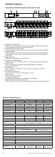
Product Features Front/Rear Panel Description (1U 15A series) A B C D E F G Source Output - Normal - Warning - Overload B Serial Port Enter PDU20SWHVIEC10ATNET QCN-0000003-00 NEMA Type Source A Select A Expansion Port Provides SNMP Card Communication J Source B 100-120V 50/60 Hz 1 H 2 3 4 5 I IEC Type 9 10 3 4 5 6 7 8 9 10 11 12 K Source B A.
Product Features Front/Rear Panel Description (1U 20A series) A B C D E F G Source Output - Normal - Warning - Overload B Serial Port Enter PDU20SWT10ATNET QCN-0000002-00 NEMA Type Source A Select A Expansion Port Provides SNMP Card Communication J Source B 100-120V 50/60 Hz 1 H 2 3 4 6 7 8 9 10 K IEC Type Source B J 200-240V 50/60 Hz Source A 5 I 1 H 2 3 4 5 6 I 7 8 9 10 K A.
Product Features Front/Rear Panel Description (2U series) A C B D E F G Source Output A Select B1 - Normal - Warning - Overload B2 Expansion Port B Provides SNMP Card Communication B3 Enter PDU30SWT17ATNET QCN-0000005-00 Serial Port NEMA Type I Source A Bank1 , 20A Bank3 , 24A Source B 100-120V 50/60 Hz 1 2 3 4 5 6 7 8 L5-30R Bank2 , 20A 17 9 10 11 12 H 13 14 15 16 K J IEC Type L I Source A Bank1 , 20A Bank3 , 24A Source B 200-240V 50/60 Hz 1 2 3 4 5 6
Installation Guide Please only use the provided screws for the entire installation process. For 1U Series Step 1. Mounting Bracket Installation Use the Mounting Bracket Screws (16) provided to attach the Mounting Brackets (2) to the ATS PDU. Step 2. ATS PDU Mounting Use the Washers (4) and Screws (4) provided to secure the ATS PDU to your existing rack system.
Installation Guide For 2U Series Step 1. Mounting Bracket Installation Use the Mounting Bracket Screws (16) provided to attach the Mounting Brackets (2) to the ATS PDU. Step 2. ATS PDU Mounting Use the Washers (4) and Screws (4) provided to secure the ATS PDU to your existing rack system. Step 3. Cord Retention Tray Installation (optional) Attach the Cord Retention Tray to the ATS PDU with the 8 Cord Retention Tray Mounting Screws provided.
Installation Guide Replacing the LCD Panel Step 1. Use a slotted screwdriver to gently lift out the LCD panel. Step 2. Disconnect the cable connector. Electrical Installation Step 1. Receptacle evaluation Ensure that the plug type of your ATS PDU unit matches the receptacles that you are using. The ATS PDU must be plugged into a three-wire, grounded utility receptacle or a UPS that is connected to a grounded utility receptacle.
Installation Guide Network Installation (Performed when a Remote Management Card is installed) Step 1. Attach the LAN Cable Using a CAT5 RJ45 cable, attach one end to the Ethernet port on the RMCard, and the other end to a network port. Step 2. Establish the ATS PDU IP address Assigning an IP address to the CyberPower ATS PDU requires the user to have an available IP address that is valid on the respective network. If an available IP address is unknown, contact the network administrator to obtain one.
Installation Guide Power Cord Retention Clip Installation- For IEC type ATS PDU Input Power Cord Retention Cable Clip Installation Step 1. Remove the screw next to the inlet. Step 2. Attach the Cable Tie on the ATS PDU and secure it with the screw removed in the previous step. Step 3. Place a Power Cord Retention Cable Clip on the power cord. Align and insert the Cable Tie into the Cable Clip as shown in the figure below. Step 4.
Installation Guide Power Cord Retention Clip Installation Step 1. Remove the screws next to the outlet where IEC Socket Power Cord Stand will be installed. Step 2. Attach the IEC Socket Power Cord Stand on the ATS PDU and secure it with the screws removed in the previous step. Step 3. Attach Cable Tie on the IEC Socket Power Cord Stand and secure it with the provided screw. Step 4. Place a Power Cord Retention Cable Clip on the power cord.
Installation Guide Removing the Power Cord Retention Clip Step 1. Remove the Power Cord Retention Clip by pushing it to the right as shown in the figure below. Step 2. Remove the Power Cord Retention Clip by pulling the clip (show in the image below) to the left. Operation Remote Management The remote management function provides for monitoring of the ATS PDU operational information, controlling outlets and utilizing SNMP functionality. Web Remote management can be performed via web interface.
Operation Local Management LCD Operation The LCD display provides instant information, such as source condition, voltage and current, for the ATS PDU. In addition, users can use the interface to configure each PDU parameters and control each outlet on the switched ATS PDU. A. Scroll Mode: The ATS PDU information will display in following order automatically when “Scroll Mode On” is configured.
Operation Environmental Monitoring (optional) The CyberPower ATS PDU with an environment sensor (ENVIROSENSOR) installed, provides remote temperature and humidity monitoring in a server closet and/or datacenter. To connect ATS PDU with ENVIROSENSOR, use RJ45 Ethernet Cable included with the ENVIROSENSOR. Plug one end into the Environmental port on the RMCARD and the other end into the RJ45 port on the ENVIROSENSOR (as shown in figures below).
Firmware Upgrade By upgrading the Firmware, you can obtain new features, updates and improvements to existing functionality. ATS PDU Update the following file to upgrade the firmware - cpsatsmafw_xxx.bin Note that the XXX is not part of the file name but is where the version number in the filename is given. Use the following steps to upgrade the firmware. 1. Download the latest firmware from cpsww.com 2. Extract the file to “C:\” 3. Open Hyper Terminal to connect the ATS PDU and use the command “@NEW” 4.
Firmware Upgrade 8. The download progress window will open after you click the Send button 9. After uploading the binary file Hyperterminal will show as below LCD Update the following file to upgrade the firmware - cpsatslafw_xxx.bin Note that the XXX is not part of the file name but is where the version number in the filename is given. Use the following steps to upgrade the firmware. 1. Download the latest firmware from cpsww.com 2. Extract the file to “C:\” 3.
Firmware Upgrade 6. Press “1” 7. Select Transfer > Send File 8. Note that the Ymodem protocol and file “C:\cpsatslafw_xxx.bin” are selected in Hyperterminal 9 The download progress window will open after you click the Send button 10. After uploading the binary file, Hyperterminal will be shown as below You can see if the firmware upgrade is successful by checking the “CyberPower System Firmware Version” after login. 18 ©2014. CyberPower Systems, Inc. All rights reserved.
Firmware Upgrade Note : 1. Please do not turn the ATS PDU off and ensure the quality of selected source power when processing firmware upgrade. The ATS PDU will not perform the ATS function when upgrading firmware. 2. Press “3” to exit the main menu of firmware upgrade. RMCARD There are two files to update in order to upgrade the firmware: - cpssnmpfw_XXX.bin - cpssnmpdata_XXX.bin Note that the XXX is not part of the file name but is where the version number in the filename is given.
Conformance Approvals FCC Warning WARNING!! This equipment has been tested and found to comply with the limits for a Class A Digital Device, pursuant to Part 15 of the FCC Rules. These limits are designed to provide reasonable protection against harmful interference in residential installation. This equipment generates, uses and can radiate radio frequency energy and, if not installed and used in accordance with the instruction manual, may cause harmful interference to radio communications.
Customer Service & Warranty Who Is Covered? This warranty only covers the original purchaser. Coverage ends if you sell or otherwise transfer the Product. How Do You Get Service? 1. You can use the contact information mentioned above for instructions. 2. When you contact CyberPower, identify the Product, the Purchase Date, and the item(s) of Connected Equipment. 3. You must provide a purchase receipt (or other proof of the original purchase) and provide a description of the defect.
Appendix A-Hyper Terminal Hyper Terminal software can be used for basic ATS PDU configuration. It utilizes a text-based interface and menu system. Navigation through the interface is done by typing the number of the menu option and pressing the Enter key. Note: The session will timeout and logout after 3 minutes of inactivity. Menu options are shown below: [Main Menu] 1. Utility Configuration 2. Outlet Manager (Switched Series Only) 3. Load Configuration 4. Network Settings 5. System Configuration 6.
Appendix B-Power Device Network Utility Overview The CyberPower Power Device Network Utility is an easy-to-use interface which is used for establishing IP addresses on CyberPower ATS PDUs. Installation Step 1. Insert the CD labeled “Software Installation CD” into the CD/DVD drive. Step 2.Select Power Device Network Utility from the installation menu (Shown in Figure 1.). Figure 1. Installation Menu Step 3. Select Next in the software wizard. Step 4. Choose an installation directory and user settings.
Appendix B-Power Device Network Utility Getting Started The Power Device Network Utility scans the network for devices with MAC addresses that match CyberPower network hardware. Once found, the device(s) can then be figured with a specific IP address, subnet mask, and gateway address. This allows the device(s) to function properly on the network and interface with CyberPower Management Console. Step 1. Select the appropriate ATS PDU from the Equipment List (Shown in Figure 4.). Figure 4.
Appendix B-Power Device Network Utility Step 3. Authentication Enter the user name and password of the ATS PDU at the Authentication menu (shown in Figure 7.) Note: The default username is “cyber” and the default password is “cyber”. Figure 7. Authentication screen Advanced Settings Timeout Settings The Timeout Setting (Shown in Figure 8.). [Edit=>Timeout Settings] is used to specify the wait time when scanning for network ATS PDUs.
CyberPower Systems, Inc. www.CPSww.