
User Manual


6
©2014. CyberPower Systems, Inc. All rights reserved.
Provides SNMP Card Communication
Expansion Port
Select
Enter
PDU20SWT10ATNET
A
B
Source Output
- Normal
- Warning
- Overload
QCN-0000002-00
Serial Port
Provides SNMP Card Communication
Expansion Port
Select
Enter
PDU20SWHVIEC10ATNET
A
B
Source Output
- Normal
- Warning
- Overload
QCN-0000003-00
Serial Port
Provides SNMP Card Communication
Expansion Port
Serial Port
Select
Enter
PDU30SWT17ATNET
A
B
Source Output
- Normal
- Warning
- Overload
QCN-0000005-00
B1
B2
B3
1 2 3 4 5 6 7 8
9 10 11 12 13 14 15 16
Source A
Source B
100-120V
50/60 Hz
Bank3 , 24A
17
Bank1 , 20A
Bank2 , 20A
L5-30R
1 2 3 4 5 6 7 8 9 10
100-120V
50/60 Hz
Source BSource A
Source A
87654321
200-240V
50/60 Hz
Source B
9 10
87654321
Source A
1211109
200-240V
50/60 Hz
Source B
Source A
Source B
200-240V
50/60 Hz
87654321 9
1716151413121110 18
Bank3 , 24A
Bank1 , 20A
Bank2 , 20A
19
L6-30R
A B C D E F
G
A B C D E F
G
1 2 3 4 5 6 7 8 9 10
100-120V
50/60 Hz
Source BSource A
H I K
J
H I K
J
H I K
J
H I K
J
A B
C D E
F
G
H
H
K
K
J
I
I
J
L
L
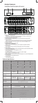
NEMA Type
IEC Type
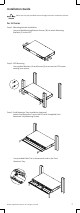
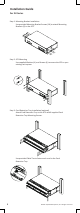
A. SNMP/HTTP Network Slot
Allow users to remotely control and monitor ATS when installed with
CyberPower’s Remote Management Card.
B. Serial Port (RJ45 modular port)
Use serial port to connect with PC and execute local control of ATS.
C. Source Indicator
Indicate Source A or B is in use. When both sources are normal, selected source
shows constant green LED while another source shows blinking green LED.
D. Output Indicator
Indicate load condition of the ATS.
E. Multifunction LCD Readout
Display various ATS information such as power and load condition.
F. Select Button
Use to select among a variety of information the LCD can display.
G. Enter Button
Use to choose selected item, enter to next level menu or return to previous menu.
H. AC Inlet/AC Power Cord
Use to connect ATS to utility power or UPS.
I. AC Output Outlets
Provide connected equipment continuous power supply.
J. Outlet Indicator (switched series only)
When the LED is on, the outlet can provide power to connected equipment.
K. Circuit Breaker
Provide output overload protection.
L. Ground Stud
Use to ground the ATS.
Technical Specifications
Switched Series Metered Series
Model Name PDU30SWT17ATNET PDU30SWHVT19ATNET PDU30MT17AT PDU30MHVT19AT
Input
Nominal Voltage 100-120V 200-240V 100-120V 200-240V
Frequency 50/60Hz
Derated Input Current 24A
Plug Type (2) NEMA L5-30P (2) NEMA L6-30P (2) NEMA L5-30P (2) NEMA L6-30P
Power Cord Type SR (10 AWG)
Power Cord Length 10 ft/3.05 m
Output
Nominal Voltage 100-120V 200-240V 100-120V 200-240V
Derated Output Current
5-20R: 16A
L5-30R: 24A
C13: 12A
C19: 16A
L6-30R: 24A
5-20R: 16A
L5-30R: 24A
C13: 12A
C19: 16A
L6-30R: 24A
Derated Output Current
(each bank)
20A
Bank Number 2
Outlet Type
(16) NEMA 5-20R
(1) NEMA L5-30R
(16) IEC C13
(2) IEC C19
(1) NEMA L6-30R
(16) NEMA 5-20R
(1) NEMA L5-30R
(16) IEC C13
(2) IEC C19
(1) NEMA L6-30R
Outlet Number 17 19 17 19
Circuit Breaker Yes
Transfer Time
Typical: 8-12ms
16ms max @ 60Hz/ 18ms max @ 50Hz
Management and Communications
Multifunction LCD Readout Voltage, Frequency, Load, Current, HW/FW Version, Network Information
Software PowerPanel® Business Edition
SNMP/ HTTP Capable Yes, with RMCARD203
Yes, with optional
RMCARD202/203
Connectivity RJ45 (Serial Port)
Sensor Capable Optional
Physical
Dimension (W x H x D) 17.05" x 3.5" x 9.3"/433mm x 88mm x 236mm
Environmental
Humidity 0 to 95% Non-condensing
Altitude 13100 ft/4000 m
Temperature 32
o
F to 113
o
F/0
o
C to 45
o
C
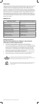
Safety Approvals
Certifications UL 60950-1, FCC Class A
* All specifications are subject to change without notice.
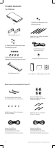
Product Features
Front/Rear Panel Description (2U series)