User Manual Power Distribution Unit www.CPSww.
Table of Contents Model List...............................................................1 Introduction............................................................1 Package Contents.................................................................. 1 For 1U Series............................................................1 For 0U Series............................................................2 For 2U Series............................................................3 Safety Precautions.................
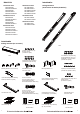
Introduction Model List 1U Switched Series 0U Monitored Series PDU15SW8FNET PDU15SWHVIEC8FNET PDU20SW8FNET PDU20SWT8FNET PDU20SWHVIEC8FNET 1U Monitored Series PDU15M8FNET PDU15MHVIEC8FNET PDU20M8FNET PDU20MT8FNET PDU20MHVIEC8FNET PDU15MV16FNET PDU20MVT24FNET PDU20MVHVT24FNET PDU30MVT24FNET PDU30MVHVT24FNET Package Contents (For 0U Series 16 Outlets/24 Outlets) 2U Switched Series PDU30SWT16FNET PDU30SWHVT16FNET 2U Monitored Series PDU30MT16FNET PDU30MHVT16FNET 0U Switched Series PDU15SWV16FNET PDU20
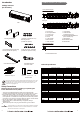
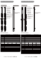
Introduction Product Features (1U 15A Series) Package Contents (For 2U Series) Front panel description NEMA Type C E D B H F YU0-0000026-00 G I Tx/Rx - Normal - Warning - Overload Amps Link Volts Select KW 1 2 3 4 5 6 7 8 PDU20SWHVIEC8FNET Reset J N A L M K F G IEC Type E PDU C D B H I Tx/Rx - Normal - Warning - Overload Amps Link Volts Select KW 1 2 3 4 5 6 7 8 J N A Mounting Brackets x 2 10 (M3x6) Cord Retention Tray Mounting Screws (Includes two spa
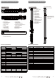
Product Features (1U 20A Series) Product Features (0U 15A Series) Front panel description Front panel description NEMA Type E C D B F G I A A Tx/Rx - Normal - Warning - Overload Amps Output 100~120VAC 50/60HZ 12A MAX Link Volts Select KW 1 2 3 4 5 6 7 8 PDU20SWT8FNET Reset J N A L M K IEC Type E C D B H F G I Tx/Rx - Normal - Warning - Overload Amps Link Volts Select KW 1 2 3 4 5 6 7 8 J PDU20SWHVIEC8FNET Reset N A L M K 1 2 I. Link Indicator J.
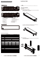
Product Features (0U 20A Series) Product Features (0U 30A Series) Front panel description NEMA Type IEC Type Front panel description NEMA Type IEC Type A A Output 200~240VAC 50/60HZ 16A MAX Output 100~120VAC 50/60HZ 16A MAX BANK 1, 15A BANK 2, 15A Output 200~240VAC 50/60HZ 24A MAX 1 2 3 4 BANK 1 5 6 7 12 AMPS B2 G Select - Normal - Warning - Overload Tx/Rx Link I F D Rear panel description A. Power Cord B. AC Output Outlets C. Input Circuit Breaker D. Current Level E. Input Voltage F.
Installation Guide Product Features (2U Series) Front panel description NEMA Type CAUTION!! C G B H Please use only the provided screws through the entire installation process. Bank 1 , 20A 100-120VAC 50/60 Hz 24A MAX 1 2 Horizontal Installation Bank 2 , 20A 8 7 6 5 4 3 YU0-0000028-00 B1 B2 - Normal - Warning - Overload Amps Volts Tx/Rx I Link J Select KW 9 10 11 12 13 14 15 16 Reset K A D E F O N M IEC Type L For 1U Model Step 1.
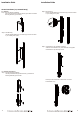
Installation Guide Installation Guide Step 3. Cord Retention Tray Installation (optional) Attach the Cord Retention Tray to the PDU with the 4 supplied Cord Retention Tray Mounting Screws. Step 2. PDU Mounting Use the supplied Washers (4) and Screws (4) to secure the PDU to your existing rack system. Use the provided Cable Ties to fasten each cord to the Cord Retention Tray. For 2U Model Step 1.
Installation Guide Installation Guide Vertical Installation (1U, 0U Model Only) For 1U Model Step 1. Mounting Bracket Installation Use the provided Mounting Bracket Screws (8) to attach the SHORT Mounting Brackets (2) to the PDU. Step 2. PDU Mounting Use the supplied Washers (2) and Screws (2) to secure the PDU to your existing rack system. Step 2. PDU Mounting Use the supplied Washers (2) and Screws (2) to secure the PDU to your existing rack system. Step 3.
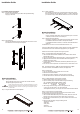
Installation Guide Installation Guide For 0U Model with Keyhole Mount Step 1. Keyhole Mount Installation Use the provided Screws (2) to attach the Keyhole Mounting Pegs (2) to the PDU. Step 3 – Attach equipment It is extremely important not to exceed the PDUs maximum current load (as outlined in the Specifications section). In order to determine your total load, simply use the Metered Readout on the front of the PDU.
Installation Guide Operation 4. Type “setup” and press Enter to enter the Authentication menu. 5. Enter the user name and password of the PDU device at the Authentication menu. Note: The default username is “cyber” and the default password is “cyber”. For further information and configuration via Hyper Terminal, see Appendix AHyper Terminal.
Operation Unattended/Automatic Shutdown PowerPanel Business Edition software automatically saves open files and gracefully shuts down the operating system in an intelligent and orderly fashion. PowerPanel must be installed on every PC for which the shut down is to take place. The PC receives SNMP messages directly from the PDU, and these messages can be scheduled for an exact date/time, or can be performed immediately. Follow the directions below for setting up Unattended/Automatic Shutdown. Step 1.
Customer Service & Warranty Customer Service & Warranty ● What are the Limitations? 1. This Warranty does not apply unless the Product and the equipment that was connected to it were connected to properly wired and grounded outlets (including compliance with electrical and safety codes of the most current electrical code), without the use of any adapters or other connectors. 2.
Appendix B-Power Device Network Utility Appendix B-Power Device Network Utility Overview The CyberPower Power Device Network Utility is an easy-to-use interface which is used for establishing IP addresses on CyberPower PDU devices. Launch Program To launch the Power Device Network Utility and get started, select Programs from the Start menu in Windows and locate the new folder and icons for Power Device Network Utility. Select Power Device Network Utility from the program folder (Shown in Figure 3.).
Appendix B-Power Device Network Utility Step 2. Assign a valid IP Address to the PDU Option 1: Assisted Setup (recommended) With the appropriate device selected from the Equipment List, open the Network Settings menu (Shown in Figure 6.). [Tools=>Device Setup]. In the Device Network Setting Menu, enter a valid IP address, subnet mask, and gateway address to setup the PDU device. Figure 6. Network Setting Menu (Device Setup) Note: The DHCP option is not available for all power devices. Step 3.