User’s Manual PR5000ELCDRTXL5U PR6000ELCDRTXL5U K01-0000166-00
IMPORTANT SAFETY INSTRUCTIONS This manual contains important instructions. Please read and follow all instructions carefully during installation and operation of the unit. Read this manual thoroughly before attempting to unpack, install, or operate the UPS. CAUTION! When installing the equipment, ensure that the sum of the leakage current of the UPS and the connected equipment does not exceed 3.5mA. CAUTION! The UPS must be connected to a grounded AC power outlet with fuse or circuit breaker protection.
INSTALLING YOUR UPS SYSTEM AUTOMATIC VOLTAGE REGULATOR(AVR) The PR5000ELCDRTXL5U/ PR6000ELCDRTXL5U stabilizes damaging inconsistent utility power. The Automatic Voltage Regulator automatically regulates low or high voltages to keep equipment working at safe AC power levels (220/230/240V) without switching to battery. Your equipment operates normally when power problems, such as, shout brownouts and blackouts.
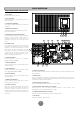
BASIC OPERATION FRONT/REAR PANEL DESCRIPTION 1. Power Switch Master On/Off switch for the UPS. 2. Power on Indicator Indicates the UPS is on and supplying power free of surges and spikes. 3. LCD Readout Toggle Button Use to rotate through multiple screens of UPS status information. 4. Multifunction LCD Readout An illuminated digital screen that displays the UPS power status information. 5.
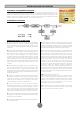
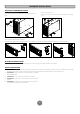
HARDWIRE THE INPUT/ OUTPUT TERMINALS CAUTION! To avoid electrical shock, before hardwiring the UPS (in/out power cord), turn the unit OFF and disconnect the unit from utility power. The in/out power cord MUST be grounded. CAUTION! To avoid electrical shock, turn off and unplug the unit first, then install the input/output power cord with grounded. Connect the ground wire prior to connecting the line wires! CAUTION! Do not use improper size power cord to avoid damaging your equipment and avoid fire hazards.
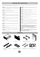
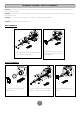
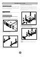
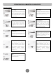
HARDWARE INSTALLATION HARDWARE INSTALLATION Step 4: Adjust rack mount rails to fit your rack These versatile UPS systems can be mounted in a rack mount or vertical /tower orientation. This versatility is especially important to growing organizations with changing needs that value having the option to position a UPS on a floor or in a rack mount system. Please follow the instructions below for the respective mounting method.
HARDWARE INSTALLATION VERTICAZL/TOWER INSTALLATION Step 1: Attach the base stands Simply slide the base stands onto the bottom of the UPS, roughly 8-10” apart. Step 2: Attach dust covers Insert dust covers into the rack mount ear screw holes that are not being used. Step 3: Rotate the Multifunction LCD Readout Separate the front panel and the UPS. Gently lift the LCD out. Rotate it to the preferred orientation. Reinstall the display for a tower configuration.
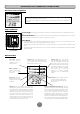
DEFINITION FOR ILLUMINATED LCD INDICATORS MULTIFUNCTION LCD READOUT The multifunction LCD readout provides ready access to power/battery condition vitals, such as: Runtime, Load, Temperature, and much more. The screen is also rotatable so the UPS can be used in either rack mount or vertical/tower orientation. BASIC OPERATION Screen toggle – To toggle through the status screens press the Select button which is located directly next to the LCD.
DEFINITION FOR ILLUMINATED LCD INDICATORS TOGGLE SCREENS Input Voltage Output Voltage The Input Voltage screen displays the AC voltage that the UPS system is receiving from the utility wall receptacle. This can be used as a diagnostic tool to identify poor quality input power. Units are listed in V (Volts). The Output Voltage screen measures, the AC voltage that the UPS is providing to your connected equipment via the UPS outlets. Units are listed in V (Volts).
LCD SETUP FUNCTIONS 1. General Mode: a.
MAINTENANCE Storage To store your UPS for an extended period, cover it and store with the battery fully charged. Recharge the battery every three months to ensure battery life. • • Battery Replacement • Please read and follow the Safety Instructions before servicing the battery. Battery replacement should be performed by trained personnel who are familiar with the procedures and safety precautions.
TECHNICAL SPECIFICATIONS Model Configuration Capacity (VA) Capacity (Watts) Energy-saving Technology Input Nominal Input Voltage Input Voltage Range Input Adjustable Voltage Range Frequency Range Input Plug Type Cold Start Output Output Voltage Note UPS Outlets On Battery Output Voltage On Battery Output Frequency Transfer Time (Typically) Overload Protection Data line Protection Surge Protection Phone / Network Protection Battery PR5000ELCDRTXL5U PR6000ELCDRTXL5U 5000VA 4000W 6000VA 4500W GreenPower U
TROUBLE SHOOTING Problem Possible Cause Circuit breaker has tripped due to an overload. Outlet does not provide power to equipment The UPS does not perform expected runtime. The UPS will not turn on. PowerPanel® Business Edition/ PowerPanel® Personal Edition Edition is inactive. Batteries are discharged. Unit has been damaged by a surge or spike. Uncritical outlets have turned off automatically due to an overload. Batteries are not fully charged. Batteries are degraded.