User’s Manual Remote Management Card RMCARD202/RMCARD203 RMCARD302/RMCARD303 Intelligent Remote Management Card allows a UPS system/environment sensor to be managed, monitored, and configured Version 1.
CyberPower Remote Management System TABLE OF CONTENTS Introduction .......................................................................................... 1 Installation Guide ................................................................................. 3 Web Interface ....................................................................................... 8 Reset to Default Setting/Recover from a Lost Password ................... 26 Firmware Upgrade .................................................
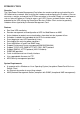
INTRODUCTION Overview The CyberPower Remote Management Card allows for remote monitoring and controlling of a UPS attached to a network. After installing the hardware and configuring an IP address, the user can access, monitor, and control the UPS from anywhere in the world! Simply use a web browser such as Internet Explorer or Firefox to access your UPS.
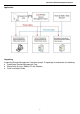
CyberPower Remote Management System Application Unpacking Inspect the Remote Management Card upon receipt.
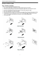
CyberPower Remote Management System INSTALLATION GUIDE Step 1. Hardware Installation Internal smart slot Remote Management Card 1. Turn off the UPS before removing the expansion port cover on the UPS. 2. Remove the two retaining screws from the expansion port cover and remove the cover. 3. Insert the CyberPower Remote Management Card into the expansion port. 4. Re-install and tighten the retaining screws. 5. Connect the Ethernet cable to the LAN port on the CyberPower Remote Management Card. 6.
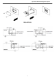
CyberPower Remote Management System RMCARD303 4
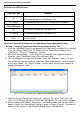
CyberPower Remote Management System Definitions for LED Indicators Link LED color Condition Off The Remote Management Card is not connected to the Network/or the Remote Management Card Power is off. On (Yellow) The Remote Management Card is connected to the Network. TX/RX LED color Off The Remote Management Card power is off. On (Green) The Remote Management Card power is on. Flash - Receiving/transmitting data packet. - Reset finished. Step 2.
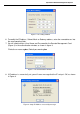
CyberPower Remote Management System Figure 2. The setting window. 6. To modify the IP Address, Subnet Mask or Gateway address, enter the new addresses into the corresponding fields. 7. You will need to enter a User Name and Password for the Remote Management Card (Figure 3) in the authentication window, as shown in figure 3. *Default user name: cyber; Default password: cyber Figure 3. The authentication window. 8.
CyberPower Remote Management System Method 2: Using a command prompt 1. Obtain the MAC address from the label on the Remote Management Card rear panel. Each Management card has a unique MAC address. 2. Use the ARP command to set the IP address. Example: To assign the IP Address 192.168.20.240 for the Remote Management Card, which has a MAC address of 00-0C-15-00-00-01, you will type in the following command prompt from a PC connected to the same network as the Remote Management Card. A.
CyberPower Remote Management System WEB INTERFACE Login Account There are two types of user account: Administrator (default username: cyber; default password: cyber) Viewer (default username: device; default password: cyber) The Administrator can access and control all functions, including enable/disable of the Viewer account. The Viewer’s access possesses read permissions for all functions but cannot control or change any settings. Note: 1.
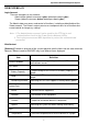
CyberPower Remote Management System Humidity The current humidity of the environment in a graph. Envir Data Name The name of the environment sensor. Location The location of the environment sensor. Recent Device Events List the latest 5 events that occurred recently. [UPS] Following items can be displayed/configured through the UPS page; however, different UPS may have different items displayed/configured.
CyberPower Remote Management System Remaining Runtime How long the UPS can support its load under battery mode. System Temperature The temperature inside the UPS. [UPS->Information] Provide the technical specifications of the connecting UPS. Information Description Model Name The model name of the UPS. Voltage Rating The output voltage rating (Volts) of the UPS. Working Frequency The output frequency rating (Hz) of the UPS. Power Rating The Volt-Amp rating of the UPS.
CyberPower Remote Management System [UPS->Configuration] Configure the parameters of the UPS. Item Definition Supplied Power Voltage Set the output voltage which is supplied to the connected equipment. Utility Power Failure Condition High/Low Input (or Output) Voltage Threshold Frequency Tolerance When the utility power voltage or output voltage (according to the UPS support) is higher/lower than the threshold, the UPS will supply battery power to the connected equipment.
CyberPower Remote Management System High/Low Bypass Voltage Power Restore Recharged Delay Recharged Capacity Returned Delay Otherwise the UPS will stop supplying output power. Check Volt Only: Only if the utility voltage is in the range of the voltage thresholds, the UPS will enter Bypass mode. Otherwise the UPS will stop supplying output power. When the UPS fault or overload occurs, the UPS will determine whether to enter Bypass mode according to the range of thresholds of utility voltage.
CyberPower Remote Management System Audible Alarm Dry Relay Function Screen Saver Time Wiring Fault Detect enabled, the UPS can be turned on without input power. If this option is enabled, the UPS will issue an audible alarm when supplying battery power or output overload. This configures the power condition for the UPS dry relay to function when the selected condition occurs. Refer to UPS manual for further information about advanced UPS dry relay utilization.
CyberPower Remote Management System [UPS->Master Switch] Switch the output power of the UPS to be on or off. Item Definition Reboot UPS Turn the UPS off and back on Turn UPS Off Turn the UPS off. UPS Sleep This command is available under Utility Power Failure Mode. It will make UPS under sleep mode until power is restored. Cancel Switch Cancel a pending action to turn the UPS off. Turn UPS On Turn the UPS on.
CyberPower Remote Management System user to verify the battery conditions and provides information about the battery, including the results and date of the last battery test. Click the Initiate button to begin a battery test. Performing a battery test is prohibited when the Frequency Working Mode option is set to fixed. If performing a battery test on the fixed frequency mode, a UPS fault may occur and cause the UPS to enter Bypass mode.
CyberPower Remote Management System [One Time]: The user may set a specific date and time for the UPS shutdown. [Per Day]: Set a specific time of the day for the UPS shutdown. [Per Week]: Set a specific day and time of the week for the UPS shutdown. 1. 2. 3. Click [One Time], [Per Day] or [Per Week] option and Click “Next>>”, Enter the date and time to shut down the UPS. Select [Never], [Immediately], or the date and time for the UPS to restore power.
CyberPower Remote Management System Maximum Minimum Contact The highest humidity as well as the time of occurrence detected by the environment sensor. The lowest humidity as well as the time of occurrence detected by the environment sensor. Display the name and status (Normal/Abnormal) of contacts. [Envir->Configuration] Item Definition Information Name The name used to identify the environment sensor. Location The place where the environment sensor is located.
CyberPower Remote Management System [Logs->Event Logs] Display the list of events and a brief description of each event along with the date and time stamp. Note: 1. The recordable events are listed under “System->Notifications->Event Action.” 2. The recorded time is using the 24-hour clock format. [Logs->Status Records] This page is used to view the logs of the UPS status and environment status; however, different product may have different items displayed.
CyberPower Remote Management System Event Logs Clear All Clear the existing event logs. The Number of Events The number of existing event logs/the max number of event logs. Save Event Logs Save the existing event logs as a txt file. Status Records Recording Interval Set the frequency to record the status data. A smaller interval will provide more frequent recordings but maintain them for a shorter period.
CyberPower Remote Management System Change Viewer account: • Select “Allow Access” to enable the Viewer account • Enter the User Name • Set the Manager IP (optional) • Enter New Password • Enter Confirm Password • Click “Apply” [System->General->Date & Time]Current Settings: Displays the current date and time on the card and allows users to set the date and time. To set the date and time, users can choose to set manually or by using the NTP (Network Time Protocol) server.
CyberPower Remote Management System - IPv6 Interface: Displays the current IPv6 address. IPv6 Gateway: Displays the current IPv6 gateway. IPv6 Configuration: - Allow Access: Set the IPv6 service to either Enable or Disable. - Router Control: The IPv6 address is assigned through the method (Stateless Address Autoconfiguration, Stateless DHCPv6 or Stateful DHCPv6) which is decided by router setting. - Manual: The IPv6 address is assigned by manuel setting.
CyberPower Remote Management System User Name Authentucation Password Privacy Password IP The name to identify SNMPv3 user. The field must be 1 to 31 characters length. The password used to generate the key used for authentication. The field must be 16 to 31 characters length. The password used to generate the key used for encryption. The field must be 16 to 31 characters length. The IP address or IP address mask can be accessed by NMS.
CyberPower Remote Management System - Log: Record the event in the “Event Logs”. E-mail: Send an email to a specific user (An available SMTP server is necessary). Trap: A SNMP trap sent to a specific IP address. SMS: Send a short message to a specific mobile phone number (An available SMS service provider is needed). [System->Notifications->SMTP Server] After setting the proper SMTP server, the UPS can send an email to users when a specific event occurs.
CyberPower Remote Management System Service provider accepts HTTP GET Service provider accepts HTTP POST Service provider accepts E-mail(SMTP) This specification from the SMS provider is required before using the HTTP GET method. Select the Using HTTP GET option in the SMS Method field. Insert the E_PHONE_NUMBER as recipient's mobile phone number and the E_PHONE_MESSAGE as event message, describe in the specification, and fill in the URL field.
CyberPower Remote Management System [System->About] Display vital information for the Remote Management Card. Item Definition Model Name Model name of the Remote Management Card. Firmware Version The version number of the current firmware installed on Remote Management Card. Firmware Updated Date The date the firmware was last updated. Hardware Version MAC Address Save Configuration Restore Configuration The hardware version of the Remote Management Card.
CyberPower Remote Management System Reset to Default Setting / Recover from a Lost Password To reset the CyberPower Remote Management Card to its default setting (including WEB log-in user name and password), please use the following steps RESET RMCARD202 RMCARD203 RESET RMCARD302 RMCARD303 1. Remove the two retaining screws on the card without turning off the UPS. 2. Uninstall the card. 3.
CyberPower Remote Management System Firmware Upgrade By upgrading the Firmware, you can obtain both the new features and updates/improvements to existing functionality. There are two files to update in order to upgrade the firmware version. RMCARD202/RMCARD203 upgrade files: (HW V2.0) A. cpsrm2sbfw_XXX.bin B. cpsrm2sbdata_XXX.bin (HW V1.0) A. cpssnmpfw_XXX.bin B. cpssnmpdata_XXX.bin RMCARD302/RMCARD303 upgrade files: (HW V2.0) A. cpsrm3sbfw_XXX.bin B. cpsrm3sbdata_XXX.bin (HW V1.0) A. cpsrm302afw_XXX.
CyberPower Remote Management System Trouble Shooting Problem Unable to configure the Management Card by method 1 or method 2 in user’s manual. Solution 1. Check the LED status, the normal condition is when yellow and green LED are both on. If green LED is off: => Check the Management Card for proper seating in the UPS and the UPS power is on. If yellow LED is off: => Ensure the network connection is valid 2. Ensure the PC being used is on the same physical network as Remote Management Card. 3.
CyberPower Remote Management System Appendix 1. IP Address Settings for CyberPower Remote Management Card Overview All devices on a computer network need to have an IP address. Each device’s IP address is unique. The same address cannot be used twice. In order to assign an IP address to the CyberPower Remote Management Card, you must determine the range of the available IP addresses, and then choose an unused IP address to assign to the Remote Management Card.
CyberPower Remote Management System If the response is shown as below, the IP address is in use. Try another IP address until an available address is found. Pinging 192.168.20.240 with 32 bytes of data: Reply from 192.168.20.240: bytes=32 time<10ms TTL=64 Reply from 192.168.20.240: bytes=32 time<10ms TTL=64 Reply from 192.168.20.240: bytes=32 time<10ms TTL=64 Reply from 192.168.20.
CyberPower Remote Management System CyberPower Systems (USA), Inc. 4241 12th Avenue East, Suite 400, Shakopee, MN 55379 Phone: (952) 403-9500 Toll-free: (877) 297-6937 Website: www.CPSww.com E-mail: tech@cpsww.com CyberPower Systems, Inc. Website: www.cpsww.