User’s Manual OL1000RTXL2U OL1500RTXL2U OL2000RTXL2U OL3000RTXL2U CyberPower Systems (USA), Inc. 4241 12th Avenue East Suite 400 Shakopee, MN 55379 Phone: 877-297-6937 Fax: 952-403-0009 www.CPSww.
IMPORTANT SAFETY INSTRUCTIONS This manual contains important instructions. Please read and follow all instructions carefully during installation and operation of the unit. Read this manual thoroughly before attempting to unpack, install, or operate the UPS. CAUTION! The UPS must be connected to a grounded AC power outlet with fuse or circuit breaker protection. DO NOT plug the UPS into an outlet that is not grounded. If you need to power-drain this equipment, turn off and unplug the unit.
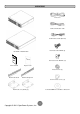
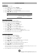
UNPACKING Phone line USB communication cable Serial Interface Cable (RS-232) Flat head screws: M5X8L (8) 1K/1.5KVA or 2K/3KVA UPS Pan head screws: M5X12L (12) User’s manual Register card Plastic washers (8) Rackmount left rail Rackmount right rail Screw hole dust covers (10) PowerPanel® Business Edition software CD Rackmount ears (Stands) (2) 2 Copyright © 2012 CyberPower Systems, Inc.
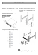
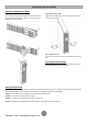
HARDWARE INSTALLATION HARDWARE INSTALLATION Step 3: Adjust rackmount rails to fit your rack These versatile UPS systems can be mounted in a rackmount or vertical tower orientation. This versatility is especially important to growing organizations with changing needs that value having the option to position a UPS on a floor or in a rackmount system. Please follow the instructions below for the respective mounting methods.
HARDWARE INSTALLATION VERTICAL/TOWER INSTALLATION Step 1: Rotate the Multifunction LCD Module Step 2: Attach the base stands Unscrew the right panel of the UPS. Separate the right panel from the UPS. Gently lift the LCD module out. Rotate it to the tower orientation. Reinstall it for a tower configuration. Tighten the screws (M5X12*4pcs) of the base stands (rackmount ears) onto the bottom of the UPS.
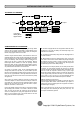
INSTALLING YOUR UPS SYSTEM SYSTEM BLOCK DIAGRAM Bypass Input Input Filter PFC AC/DC BUS Charger AC/DC Battery DC/DC Inverter DC/AC INV RY Control & Monitoring Output Filter Output LCD Module USB & DB9 SNMP Slot Line Mode Battery Mode Bypass Mode HARDWARE INSTALLATION GUIDE 1. Battery charge loss may occur during shipping and storage. Before 6. This UPS is equipped with an auto-charge feature.
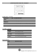
BASIC OPERATION POWER MODULE FRONT/REAR PANEL DESCRIPTION 1. Power Button / Power on Indicator Master ON/OFF for the UPS. Indicates that the UPS is on and supplying power. 2. UPS Status / Fault / Replace Battery LED Indicator Indicates the status of the UPS, displaying whether it is operating in Line, Battery or Bypass Mode, if it has an internal fault or if the battery needs to be replaced. 3. Multifunction LCD Readout Shows UPS status, information, settings and events.
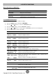
OPERATION INSTRUCTIONS FOR LCD MODULE LED INDICATORS – UPS STATUS LED Indicators Color UPS Status Description ON/OFF Blue UPS power is on. ON-LINE Green UPS is operating in Line Mode. BATTERY ON Yellow UPS is operating in Battery Mode. BYPASS Yellow UPS is operating in Bypass Mode, Manual Bypass or ECO (Economy) Mode. FAULT Red UPS has an internal fault. See “Trouble Shooting” for additional information.
LCD SETUP FUNCTIONS MULTI-FUNCTION LCD MAIN MENU Press “Enter” button to activate “MAIN MENU”. MAIN MENU submenu Function Description Information Displays the UPS information. Configure Displays the UPS settings that can be configured by the user. Event Log Displays the 3 most recent events, (day/hour/minute), and event description. by event count, time LCD INFORMATION READOUT There are 19 types of UPS information available for display. 1. Press the “ENTER” button to activate the “MAIN MENU”.
LCD SETUP FUNCTIONS LCD EVENT LOG 3 Event Logs of UPS can be recorded. 1. Press the “ENTER” button to activate the “MAIN MENU”. 2. Press the “▲” and “▼” buttons to scroll to the “Event Log” option. 3. Press the “ENTER” button to select the “Event Log” submenu. 4. Press the “▲” and “▼” buttons to scroll through the “Event Log” submenu in the following table. 5. Press the “ESC” button to return to UPS Status.
LCD SETUP FUNCTIONS Configure Submenu Available Settings Default Setting Output Voltage* = [100V] [110V] [115V] [120V] [127V] 120V Range= [+/- 1%] [+/- 2%] [+/- 3%] [+/- 4%] [+/- 5%] Sync Freq Window +/- 5% [+/- 6%] [+/- 7%] [+/- 8%] [+/- 9%] [+/-10%] Range= [+10%/-10%] [+10%/-15%] [+10%/-20%] Bypass V Window Bypass Condition +10%/-15% [+15%/-10%] [+15%/-15%] [+15%/-20%] [Check Freq/Volt] [Check Volt Only] [No Bypass] Check Freq/Volt [Disable] [Enable] Disable ECO Mode** [V Range= +/-15%] [V R
LCD MODULE REMOTE CONTROL and WALL-MOUNTING INSTRUCTIONS REMOTE CONTROL WALL-MOUNTING INSTRUCTIONS Step 1: Remove the Multifunction LCD Module Step 1: Remove the Multifunction LCD Module Unscrew the right panel of the UPS. Separate the right panel from the UPS. Gently lift the LCD module out. Reinstall the right panel. Unscrew the right panel of the UPS. Separate the right panel from the UPS. Gently lift the LCD module out. Reinstall the right panel.
MAINTENANCE CAUTION! Do not open or mutilate the batteries. Electrolyte fluid is harmful to the skin/eyes and may be toxic. CAUTION! To avoid electric shock, turn off and unplug the UPS from the wall receptacle before servicing the battery. CAUTION! Only use tools with insulated handles. Do not lay tools or metal parts on top of the UPS or battery terminals. Storage To store your UPS for an extended period, cover it and store with the battery fully charged.
TECHNICAL SPECIFICATIONS Model Configuration Capacity (VA) Capacity (Watts) Form Factor Energy-saving Technology Input Input Voltage Range Input Frequency Range Input Power Factor Cold Start Output Output Waveform Output Voltage* Output Frequency Transfer Time (Typically) Rated Power Factor Harmonic Distortion Crest Factor ECO Mode Voltage Regulation UPS Outlets Protection Surge Protection Phone / Network Protection Overload Protection Short Circuit Protection Battery Specifications Recharge Time (Typically
TROUBLE SHOOTING Problem Warning O/P Overload Load Over XXX% Battery Mode Possible Cause Solution Your equipment requires more power than the UPS can provide. If the UPS is in Line Mode then it will transfer to Bypass Mode; if the UPS is in Battery Mode it will shutdown. Your equipment requires more power than the setting in the Power Management Software ® (PowerPanel Business) will allow. BAT Disconnected Battery Failure UPS has failed a Battery Test.
PRODUCT REGISTRATION CyberPower requests that you complete and return the Warranty Registration Card enclosed with the Product or register the Product at its website (www.cpsww.com) to establish that you are the Initial Customer of the Product, and therefore entitled coverage under the Limited Warranty and the Connected Equipment Guarantee. (Registration is not required for coverage, but note: if you do not register your purchase, you will be required to provide proof of purchase.
LIMITED WARRANTY AND CONNECTED EQUIPMENT GUARNTEE Who Pays For Shipping? We pay when we send items to you; you pay when you send items to us. What Are Some Examples Of What This Warranty Does Not Cover? 1. This Warranty does not cover any software that was damaged or needs to be replaced due to the failure of the Product or any data that is lost as a result of the failure or the restoration of data or records, or the reinstallation of software. 2.
CONFORMANCE APPROVALS FCC Notice This device complies with part 15 of the FCC Rules. Operation is subject to the following two conditions: (1) This device may not cause harmful interference, and (2) this device must accept any interference that may cause undesired operation. WARNING!! This equipment has been tested and found to comply with the limits for a Class A digital device, pursuant to part 15 of the FCC Rules.