
Owners manual

EC350G / EC550G / EC750G
EC650LCD / EC850LCD
User’s Manual
K01-0000277-00
Thank you for purchasing a CyberPower product. Please take a few minutes to register your product at www.cpsww.com/registration.
Registration certifies your product's warranty, confirms your ownership in the event of a product loss or theft and entitles you to free technical
support.
(SAVE THESE INSTRUCTIONS)
This manual contains important safety instructions. Please read and follow all instructions carefully during installation and operation of the unit.
Read this manual thoroughly before attempting to unpack, install, or operate your UPS.
CAUTION! To prevent the risk of fire or electric shock, install in a temperature and humidity controlled indoor area free of conductive
contaminants. (Please see specifications for acceptable temperature and humidity range).
CAUTION! To reduce the risk of electric shock, do not remove the cover. There are no user serviceable parts inside.
CAUTION! Hazardous live parts inside can be energized by the battery even when the AC input power is disconnected.
CAUTION! The UPS must be connected to an AC power outlet with fuse or circuit breaker protection. Do not plug into an outlet that is not
grounded. If you need to de-energize this equipment, turn off and unplug the unit.
CAUTION! To avoid electric shock, turn off the unit and unplug it from the AC power source before installing a computer component.
CAUTION! Not for use in a computer room as defined in the Standard for the Protection of Electronic Computer/Data Processing Equipment,
ANSI/NFPA 75.
CAUTION! To reduce the risk of fire, connect only to a circuit provided with 20 amperes maximum branch circuit over current protection in
accordance with the National Electric Code, ANSI/NFPA 70.
CAUTION! Risk of explosion if battery is replaced by an incorrect type. Batteries shall be installed by service personnel, and the replacement of
batteries with a suitable recommended type. Dispose of used batteries according to the instructions.
CAUTION! Do not dispose of batteries in a fire. The batteries may explode.
CAUTION! Do not open or mutilate batteries. Released electrolyte is harmful to the skin and eyes. It may be toxic.
DO NOT USE FOR MEDICAL OR LIFE SUPPORT EQUIPMENT! CyberPower Systems does not sell products for life support or medical
applications. DO NOT use in any circumstance that would affect operation and safety of life support equipment, any medical applications or
patient care.
DO NOT USE WITH OR NEAR AQUARIUMS! To reduce the risk of fire or electric shock, do not use with or near an aquarium. Condensation
from the aquarium can cause the unit to short out.
UNPACKING
Inspect the UPS upon receipt. The box should contain the following:
(a) UPS unit (b) User’s manual (c) USB device cable
*PowerPanel® Personal Edition software is available on our website. Please visit www.cpsww.com and go to the Software Section for
free download.
HOW TO DETERMINE THE POWER REQUIREMENTS OF YOUR EQUIPMENT
1. Ensure that the equipment plugged into the UPS does not exceed the UPS unit’s rated capacity (350VA/255W for EC350G, 550VA/330W for
EC550G, 750VA/450W for EC750G, 650VA/390W for EC650LCD, and 850VA/510W for EC850LCD). If the rated capacities of the unit are
exceeded, an overload condition may occur and cause the UPS unit to shut down or the circuit breaker to trip.
2. There are many factors that can affect the amount of power that your electronic equipment will require. For optimal system performance
keep the load below 80% of the unit’s rated capacity.
HARDWARE INSTALLATION GUIDE
1. Your new UPS may be used immediately upon receipt. However, after receiving a new UPS, to
ensure the battery’s maximum charge capacity, it is recommended that you charge the battery
for at least 8 hours. Your UPS is equipped with an auto-charge feature. When the UPS is
plugged into an AC outlet, the battery will automatically charge when it’s turned on or turned off.
2. With the UPS unit turned off and unplugged, connect your computer, monitor, and any other
peripherals requiring battery backup from the SURGE/BATTERY outlets. Plug the other peripheral equipment (e.g. printer, scanner,
speakers, etc.) into the full-time surge protection outlets. DO NOT plug a laser printer, paper shredder, copier, space heater, vacuum
cleaner, sump pump, or other large electrical device into the “Battery and Surge Protected Outlets”. The power demands of these
devices will overload and possibly damage the unit.
3. To protect a fax, phone, or modem line, connect a telephone cable from the wall jack outlet to the IN jack of the UPS.
Connect a telephone cable from the UPS OUT jack to protect a modem port on the computer, a telephone, or fax machine.
4. Plug the UPS into a 2 pole, 3 wire grounded receptacle (wall outlet). Make sure the wall branch outlet is
protected by a fuse or circuit breaker and does not service equipment with large electrical demands (e.g. air
conditioner, refrigerator, copier, etc.). The warranty prohibits the use of extension cords, outlet strips,
and surge strips in conjunction with the UPS unit.
5. Press the power switch to turn the unit on. The Power On indicator light will illuminate green and the unit will “beep” twice.
6. If an overload is detected, an audible alarm will sound and the unit will emit one long beep. To correct this, turn the UPS off and unplug at
least one piece of equipment from the battery power supplied outlets. Make sure the circuit breaker is depressed and then turn the UPS on.
7. To maintain optimal battery charge, leave the UPS plugged into an AC outlet at all times.
8. To store the UPS for an extended period of time, cover it and store with the battery fully charged. While in storage, recharge the battery
every three months to ensure optimal battery life.
9. Ensure the wall outlet and UPS are located near the equipment being attached for proper accessibility.
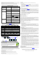
DESCRIPTION
1. Battery and Surge Protected Outlets
The unit has battery powered/surge suppression outlets to ensure temporary uninterrupted operation of your equipment during a power
failure. (DO NOT plug a laser printer, paper shredder, copier, space heater, vacuum cleaner, sump pump, or other large electrical
device into the “Battery and Surge Protected Outlets.” The power demands of these devices will overload and possibly damage
the unit.)
2. Full-Time Surge Protection Outlets / ECO Controlled Outlets
The unit has surge suppression outlets to provide surge and line noise protection. Three of the surge-only outlets are also ECO controlled
outlets.
3. Power Switch
To turn the UPS ON, press the power button for approximately 2 seconds - you will hear a constant tone (1 second) - and release after a
short beep.
To turn the UPS OFF, press the power button for approximately 2 seconds - you will hear a constant tone (1 second) - and release after two
short beeps.
Alarm setting: The audible alarm can be turned Off or On by quickly pressing the POWER button twice. The default setting is for the Alarm
On. To turn the Alarm Off, quickly press the power button twice. You will hear two short beeps when the Alarm is turned Off. To turn the
Alarm back On, quickly press the power button twice. You will hear a single short beep when the Alarm is turned On. *When the Alarm is
turned Off, there will be no audible notification when the UPS reaches a low battery state.
4. Power On Indicator (green)
This LED is illuminated when the utility power is normal and the UPS outlets are providing power, free of surges and spikes.
5. Mode Switch (EC650LCD and EC850LCD only)
Press the Mode Switch for approximately 3 seconds to enter setup mode to select four functions: Utility High Voltage Range, Utility Low
Voltage Range, ECO ON/OFF, and LCD sleep ON/OFF. When a function is selected, press Mode Switch for 3 seconds to view options.
When an option is selected, wait for 8 seconds for the setting to be confirmed. After the setting has been confirmed the LCD screen will
leave setup mode and go back to status display. If there is no action for 8 seconds during setup, the LCD will also leave setup mode and go
back to the status display.
a. Utility High Voltage Range: Adjust the value of high voltage range.
b. Utility Low Voltage Range: Adjust the value of low voltage range.
c. ECO: Eon/EoF (ON/OFF): Turn on or turn off ECO function. For more information, refer to ECO Function Setup section.
d. LCD: L1/L0 (ON/OFF):
* When LCD is set to L1, LCD will be always ON. When LCD is set to L0, LCD will dim if untouched for 1 minute.
* In battery mode, LCD is always on regardless if the setting is L1 or L0.
ECO Button (EC350G, EC550G, and EC750G only)
Press ECO button for 3 seconds to turn on or turn off ECO function in line mode.
6. ECO Indicator
ECO Indicator shows the condition of ECO function. For more information, refer to ECO Function Setup section.
7. Communication Protection Ports
Communication protection ports will protect any standard modem, fax, or telephone line. (RJ11)
8. Circuit Breaker
Located on the side of the UPS, the circuit breaker serves to provide overload and fault protection.
9. USB Port to PC
The USB port allows connection and communication between the USB port on the computer and the UPS unit. The UPS communicates its
status to the PowerPanel
®
Personal Edition software. The USB port is also used for operating the UPS in ECO mode. For more information,
refer to ECO Function Setup section.
10. Outlets Designed for AC Adapters
The UPS unit has 4 widely-spaced outlets so AC power adapters can be plugged into the UPS without overlapping or blocking adjacent
outlets.
ECO FUNCTION SETUP
ECO Function
When the ECO function is active the UPS can detect whether the PC that is connected to the USB port is turned on or off. If the PC is turned
off, the UPS will turn off the ECO controlled outlets and cut power to the devices connected to them in order to save power. Generally, these
are peripherals that are not used when the PC is not turned on.
ECO Controlled Outlets
Three of the surge-only outlets are also ECO controlled outlets. When the PC that is connected to the USB port is turned off, the UPS will
turn off the ECO controlled outlets to save energy.
ECO Setup
1. The factory default setting is OFF. ECO mode can only be enabled/disabled and will only be active when the UPS is receiving utility
power and not in battery mode.
2. For the EC650/850LCD, press the Mode switch for approximately 3 seconds to enter setup mode and select the ECO function. When
the ECO function is selected, press the Mode switch for 3 seconds to turn the function ON or OFF. Once ON or OFF is selected, wait 8
seconds for the setting to be confirmed and the LCD screen will return to status mode. For the EC350/550/750G, press the ECO button
for 3 seconds to turn ON or OFF the ECO function.
3. When the ECO function is OFF, utility power from the ECO outlets will always be on. When the ECO function is ON, utility power from
the ECO outlets will turn off if the PC connected to the UPS via the USB port is turned off or if there is no PC is connected to the UPS via
USB.
ECO Indicator
The LED will be blinking when the ECO function is turned ON but the PC is either off or not connected. The LED will be solid if the ECO
function is turned on and the connected PC is on. The LED is off when the ECO function is disabled. See below table for more information.
ECO Indicator ECO Function ECO Outlet Status Condition
Solid (green) ON With Utility Power When PC is ON and USB port on the UPS is connected, Peripherals
will receive power to operate.
Blinking ON Without Utility Power When PC is OFF or the USB port on the UPS is not connected, power
to the Peripherals will be turned off.
OFF OFF Always with Utility
Power
When PC is ON/OFF, Peripherals is always ON.
DEFINITIONS FOR ILLUMINATED LED INDICATORS
Power ON
Alarm
CONDITION
On
Off Normal
On
Beep twice
every 30 seconds
Utility Failure- The UPS is providing power to battery power-supplied
outlets from its battery.
On
Rapid Beeping
every 1/2 second
Utility Failure- The UPS is providing battery power. Rapid beeping
indicates the unit will run out of power shortly.
Off
Constant tone
Battery Overload - Occurs when connected equipment exceeds the
listed capacity of the UPS. Turn the UPS off, unplug at least one
piece of equipment from battery outlets, wait 10 seconds, reset the
circuit breaker and turn the unit on.
INPUT voltage meter: This meter measures the AC voltage that the UPS system is receiving from the
utility wall outlet. The UPS is designed to continuously supply connected equipment with stable output
voltage. In the event of a complete power loss, severe brownout, or over-voltage, the UPS relies on its
internal battery to supply consistent 110/120 output voltage. The INPUT voltage meter can be used as
a diagnostic tool to identify poor-quality input power.
OUTPUT voltage meter: This meter measures, in real time, the AC voltage that the UPS system is
providing to the computer during normal AC/Utility Power mode, and battery backup mode.
ESTIMATE RUN TIME: This displays the run time estimate of the UPS with the current battery
capacity and load.
NORMAL icon: This icon appears when the UPS is working under normal conditions.
BATTERY icon: During a severe brownout or blackout, this icon appears and an alarm sounds (two short beeps followed by a pause) to indicate
the UPS is operating from its internal battery. The alarm will continue to sound during a prolonged brownout or blackout. The BATT.CAPACITY
meter will show one 20% capacity segment remaining to indicate the UPS's battery is nearly out of power. You should save files and turn off your
equipment immediately.
BASIC OPERATION
INSTALLING YOUR UPS SYSTEM
IMPORTANT SAFETY WARNINGS
DEFINITIONS FOR ILLUMINATED LCD INDICATORS
The LCD display indicates a variety
of UPS operational conditions. All
descriptions apply when the UPS is
plugged into an AC outlet and turned
on or when the UPS is on battery.
PRODUCT REGISTRATION
EC650LCD (8 outlets)
EC850LCD
(12
outlets)
EC350G / EC550G (8 outlets)
EC750G
(12 outlets)