
User's Manual

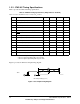
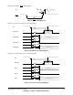


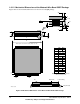

Table Of Contents
- 1.1 Overview
- 1.2 General Parameters
- 1.3 Electrical and Thermal Characteristics
- 1.4 Pinout Diagram
- 1.5 Pinout Listing
- 1.6 Package Description
- 1.7 System Design Information
- 1.8 Ordering Information
- A.1 Package Environmental, Operation, Shipment, A....
- A.2 Card Assembly Recommendations

18 603 Hardware Specifications, REV 2
Preliminary—Subject to Change without Notice
1.6.1.2 Mechanical Dimensions of the Motorola Wire-Bond CQFP Package
Figure 10 shows the mechanical dimensions for the wire-bond CQFP package.
Figure 10. Mechanical Dimensions of the Motorola Wire-Bond CQFP Package
*Reduced pin count shown for clarity. 60 pins per side
Min. Max.
A 30.86 31.75
B 34.6 BSC
C 3.75 4.15
D 0.5 BSC
E 0.18 0.30
F 3.10 3.90
G 0.13 0.175
H 0.45 0.55
J 0.25 –
AA 1.80 REF
AB 0.95 REF
θ12°6°
θ21°7°
R 0.15 REF
–H–
AB
θI
R
R
AA
θ2
H
Pin 240
C
A
B
Pin 1
DE
*Not to scale
G
F
J
Die Wire Bonds Ceramic Body
Alloy 42 Leads
Notes: 1. BSC—Between Standard Centers.
2. All measurements in mm.