
User's Manual
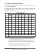

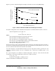
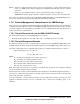
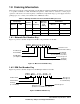

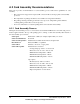

Table Of Contents
- 1.1 Overview
- 1.2 General Parameters
- 1.3 Electrical and Thermal Characteristics
- 1.4 Pinout Diagram
- 1.5 Pinout Listing
- 1.6 Package Description
- 1.7 System Design Information
- 1.8 Ordering Information
- A.1 Package Environmental, Operation, Shipment, A....
- A.2 Card Assembly Recommendations

603 Hardware Specifications, REV 2 23
Preliminary—Subject to Change without Notice
Figure 13 provides a thermal management example for the Motorola wire-bond CQFP package.
Figure 13. Motorola Wire-Bond CQFP Thermal Management Example
The junction temperature can be calculated from the junction-to-ambient thermal resistance, as follows:
Junction temperature: T
j
= T
a
+ R
θja
* P
or
T
j
= T
a
+ (R
θjc
+ R
cs
+ R
sa
) * P
Where:
Ta is the ambient temperature in the vicinity of the device
R
θja
is the junction-to-ambient thermal resistance
R
θjc
is the junction-to-case thermal resistance of the device
R
cs
is the case-to-heat sink thermal resistance of the interface material
R
sa
is the heat sink-to-ambient thermal resistance
P is the power dissipated by the device
In this environment, it can be assumed that all the heat is dissipated to the ambient through the heat sink, so
the junction-to-ambient thermal resistance is the sum of the resistances from the junction to the case, from
the case to the heat sink, and from the heat sink to the ambient.
Note that verification of external thermal resistance and case temperature should be performed for each
application. Thermal resistance can vary considerably due to many factors including degree of air
turbulence.
For a power dissipation of 2.5 Watts in an ambient temperature of 40
°C at 1 m/sec with the heat sink
measured above, the junction temperature of the device would be as follows:
T
j
= T
a
+ R
θja
* P
T
j
= 40 °C + (10 °C/Watt * 2.5 Watts) = 65 °C
which is well within the reliability limits of the device.
0123 5
0
5
10
15
20
25
30
35
Motorola Wire-Bond CQFP
With Heat Sink
Forced Convection (m/sec)
Junction-to-Ambient Thermal
Resistance (°C/watt)
4