
User`s manual


CYCOM 485 User's Guide
However your computer works, you must have only one COM device per COM address/interrupt. If you have
two, neither will work.
Cabling
Cabling to the CYCOM 485 is through a 9-pin, D-type female connector. The CBL 09xxMM is compatible
with these connectors.
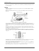
Figure 3 is a sample RS485 cable with power to a remote module. Multiple modules may be added to the
RS485 link.
Figure 3. RS485 Cable CYCOM 485 to Remote Module
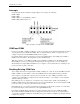
The pin assignments of this connector are shown in Figure 4. Note: Pins 4 and 8 and pins 5 and 9 are tied
together on the board. Only three wires are needed for RS-485 communication. One must be connected to pins
4/8 and the other to pins 5 or 9 to provide the differential communication line. The third wire is for a ground
reference.
We strongly recommend that you use the fused ground for the signal ground line. This fuse will protect the
C
YCOM 485 and the computer from earth ground differences, voltage spikes and transients which could subject
the C
YCOM 485 to potentially hundreds of volts!
If remote data acquisition modules are being used with the C
YCOM 485, those should be powered through a
separate power supply. The power supplies for all devices connected to a C
YCOM 485 should share the same
earth ground.
Figure 4. 9-Pin Board Connector
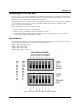
Note that there are two 9-pin connectors on the board (Figure 5). These two connectors are wired in parallel.
(A connection to pin 9 on one connector is the same as a connection to pin 9 on the other.)
There is only one communications chip on the C
YCOM 485. There are twos connectors to ease cabling from
one PC to multiple drops on the RS-485 serial line.
If your application requires more than 31 remote devices, you will need to install a second C
YCOM 485. The
RS485 standard supports up to 32 separate devices on a single transmission wire pair.
10