Configuration Utility User’s Guide Revision 0.
1 Introduction........................................................................................................................... 3 1.1 List of abbreviations and Terms............................................................................................ 3 2 Installation............................................................................................................................. 4 3 Using the TI WLAN CU........................................................................
1 Introduction The configuration utility provides displaying and changing parameters of the TI WLAN driver. 1.1 List of abbreviations and Terms AES AP BSS BSSID CU FCS GUI IBSS LEAP MAC MSDU PBCC PRS RSSI SSID SSN TI TKIP WEP WiFi WPA WLAN Revision 0.
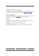
2 Installation Revision 0.
3 Using the TI WLAN CU Important Notes: • In case that the device was not installed properly or that it is disconnected, all buttons, combo boxes, edit boxes etc. will be disabled. Also the status text in the main window will be set to Driver not loaded. • To save any changes – press the Apply button. Changes will not be saved if changed focus to another tab without previously clicking the Apply button.
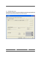
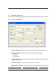
3.1 The Main (Status) Screen The Main Screen is the main page for the CU. It contains the available 802.11 networks and the current configuration basic data. It enables rescanning the network, modifying the current configuration parameters and connecting to each one of the listed SSIDs. It also enables activating and deactivating of using an external configuration. Revision 0.
Getting Started: In order to connect to a network, do the following: 1) In the Available Networks Window the currently available networks are displayed. In order to connect to a specific network – select the appropriate raw (will be highlighted as a result) 2) Click on the Connect button (another option is to double click the appropriate raw). After doing so, the CU will attempt associating with the chosen network.
Modifying Current Connection Parameters To modify the current connection parameters, click the Modify button. So, a new property sheet will be opened. This property sheet contains two pages named ‘”New connection” and “Advanced”, see section 3.2.1 , see section 3.2.2 . Advanced Configuration Check the External Configuration check box for enabling privacy external configuration. By doing so, all three buttons (Connect, Modify and Rescan) will be disabled, see section 3.4 – Privacy Screen for more details.
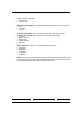
3.2 The Modify Property Sheet Both New Connection and Advanced page contains the current connection modifiable parameters retrieved from the driver. 3.2.1 The New Connection tab • Preferred SSID – preferred Service Set Identifier - a string identifying the current configured service set. • BSS Type combo box – Basic Service Set Type. This field can be one of the following: o 802.11 Ad hoc o Infrastructure o High-speed Ad hoc • Tx Rate combo box – Current rate used for transmitting frames.
• This field contains the following values: o No Power Save o Max Power Save • IBSS Protection combo box – Independent Basic Service Set protection can be one of the following: o o o • • 4x Config radio button – select “4x enable” to enable 4x mode, and “4x disable “to disable it. Tx Power Level combo box – Transmit power level. Can be one of the following: o o o o o • Low Power Medium-Low Power Medium-Power Medium-High Power High Power Mode combo box – selection of one of the standard 802.
3.2.2 • Advanced tab Fragment Threshold edit box- the range of selectable values is 0 – 2347 inclusive. 2347 is the default value. • RTS Threshold edit box - the range of selectable values is 0 – 2346 inclusive. 2346 is the default value. • • Preamble - the user can select either short or long. Authentication combo box – Can be one of the following values: o o o • Auto Switch Shared Key Open System 802.
• 3.3 Retry limits Long edit box - the range of selectable values is 0 – 15. The Advanced Properties Screen Read only advanced data for current configuration. Most of the parameters are those previously defined in the Modify property sheet. Additional parameters: Left Side: • • Authentication – defined in the Privacy screen. See next section for more details. AP Tx Power Level – Current AP Tx power level in mW. Revision 0.
Network Information • IP Address • Net. Mask • Gateway Right side: • Encryption – defined in the Privacy screen. See next section for more details. • Regulatory Domain For 2.4 GHz: o FCC o IC o ETSI o Spain o France o MKK o MKK1 o Unknown For 5 GHz: o US o World Band o Extended World Band – can be one of the following: • MAC Addr - MAC address • Country Code – represented by a 3 maximum length string. Revision 0.
3.4 The Privacy Screen Note: This window will be disabled in case that the External Configuration check box (in the Main window) was checked. In this screen the privacy mode is being configured. There are 3 optional privacy modes: • • • None – no security defined. WEP -for WEP key defining. Press the Select button to change WEP configuration. A new dialog window will be opened (see section 3.4.1). CCX - for CCX configuration. Press the Select button to change CCX configuration.
To use the external mode (privacy configured by Funk’s Odyssey software), check the External Configuration check box in the main dialog and press the Apply button. All privacy configurations will be disabled, until you uncheck the External Configuration check box. 3.4.1 The WEP Screen Configure WEP keys: • Choose key size form the key • • • size combo box. Available values - 40 bit, 128 bit, 256 bit. Add an encryption string within the Encryption edit box.
3.4.2 The CCX Configuration Screen Select an option from the Network Security Type combo box. Available options are: • None – choosing it will enable the WEP Select button. By pressing it you will get to the same window as described in see section 3.4.1 • LEAP – choosing it will enable the Leap Credentials group box, where you can type the user ID and password. • External –external CCX configuration.
3.5 The Statistics Screen Contains general statistics data retrieved from the driver. Revision 0.
3.6 The About Screen The about screen contains general version data. Revision 0.
3.7 3.7.1 Debug Screen Debug Tab activation Add the following text to shortcut definition as it shown on picture below. Revision 0.
3.7.2 Debug Screen options The debug screen is used for directly accessing the hardware. Revision 0.
Federal Communication Commission Interference Statement This equipment has been tested and found to comply with the limits for a Class B digital device, pursuant to Part 15 of the FCC Rules. These limits are designed to provide reasonable protection against harmful interference in a residential installation. This equipment generates, uses and can radiate radio frequency energy and, if not installed and used in accordance with the instructions, may cause harmful interference to radio communications.
This device is intended only for OEM integrators under the following conditions: 1) The antenna must be installed such that 20 cm is maintained between the antenna and users, and 2) The transmitter module may not be co-located with any other transmitter or antenna. As long as 2 conditions above are met, further transmitter test will not be required.