
Service manual


suspect the lower board and then the display board. This signal can also be seen on a
diagnostic LED of the display board.
If the drive motor (and running belt) does not rotate at all, the problem is more difficult to
diagnose. First, suspect the power relay and check it by going into diagnostics, d13, and
press the v elevation button in conjunction with the SPEED + button. This will toggle the relay
on/off. You should be able to hear the relay toggle and note as well that the value in the right
window reads “1.” If it reads zero, the problem is most likely the console cable.
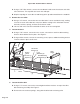
If none of these prove to be the problem, have a qualified service technician check the wiring
for wear or abrasion and also inspect the motor brushes. Any arcing, pitting or burning of the
brushes, or a brush that is less than .438” (7/16"/11.13mm) indicates the need for brush
replacement. The tightness of the brush cap and brush holder mount in the drive motor
housing should also be checked. NOTE: There are two lower board fuses which allow power
to the display and to the motor drives. The upper display is not likely to light up at all if one or
both of the fuses need to be replaced. Have a qualified service technician replace these only
with equivalent value fuses.
ERR 2: Excessive Current Draw
This error code is generated by exceeding the current limit of the motor drive system for two
seconds. The error is generated to help prolong the life of the treadmill and alert the owner to
a potentially damaging situation. Most common occurrences of this are high belt/deck friction
due to wear or contamination, a worn motor, or a breakdown of the choke. Problems in the
drive motor brush area, such as worn, pitted or arcing motor brushes, a loose drive motor
brush cap, or a loose drive motor brush holder can also cause this error code to be
generated.
Another source of this problem could be excessive friction between the deck and belt, usually
caused by a lack of routine belt/deck cleaning, or by a worn deck (see the Preventive
Maintenance chapter).
A third cause for this code could be a defective choke or a poor connection at the choke
assembly.
Last, the failure of an electronic component in the motor control or loss of magnetism in the
drive motor permanent magnet could also generate this error code.
ERR 3: Loss of Speed Signal
This error code occurs after the treadmill has successfully started, and indicates that the
computer in the display control panel has lost the motor speed signal from the speed sensor.
The causes for this error are similar to those listed for Error 1.
ERR 4: No Frequency Lock
This error code can occur when the treadmill is powered on by turning the main ON/OFF
switch to the ON position and the treadmill is unable to identify the frequency of the supply
Cybex 700T Treadmill Owner’s Manual
Page 7-12