AutoView 200 Installer/User Guide
AutoView 200 Installer/User Guide
AutoView 200 Installer/User Guide Cybex Computer Products International Ltd. Cybex House Shannon Free Zone Shannon, Co. Clare, Ireland (Tel) 00353 61 471 877 (Fax) 00353 61 471 871 www.cybex.ie ©1999 Cybex Computer Products Corporation. All rights reserved. IBM, PC/AT and PS/2 are registered trademarks of International Business Machines Corporation. ScrollPoint is a trademark of International Business Machines Corporation. Expert Mouse is a registered trademark of Kensington Technology Group.
AutoView 200 Installer/User Guide FCC Notification Warning: Changes or modifications to this unit not expressly approved by the party responsible for compliance could void the user's authority to operate the equipment. Note: This equipment has been tested and found to comply with the limits for a Class A digital device, pursuant to Part 15 of the FCC Rules. These limits are designed to provide reasonable protection against harmful interference when the equipment is operated in a commercial environment.
Table of Contents Chapter 1 - Product Overview Feature Overview ...................................................................................................................................... 1 Compatibility ............................................................................................................................................. 3 Chapter 2 - Installation Basic Install .................................................................................................................
AutoView 200 Installer/User Guide INSTRUCTIONS: The exclamation point within an equilateral triangle is intended to alert the user to the presence of important operating and maintenance (servicing) instructions in the literature accompanying the appliance.
1 Product Overview Feature Overview The AutoView 200 allows you to control up to 64 PCs with one keyboard, monitor and mouse. Each computer can be up to 30 feet away from the AutoView 200. It also provides you with the added benefit of being able to add a second user up to 500 feet away from the AutoView system. The AutoView 200 works with IBM PC/AT and PS/2 systems, and 100% compatible machines with support for VGA, SVGA, XGA and XGA-II video.
AutoView 200 Installer/User Guide PS/2 mouse translation For added compatibility with your current equipment, AutoView 200 features PS/2 mouse translation capability. Operated through the AutoView 200, your PS/2 mouse will work with any attached PC regardless of whether the computer is serial or PS/2 mouse compatible! Expansion for up to 64 computers An AutoView 200 unit will support from one to eight attached PCs, or channels.
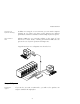
Product Overview Push-button & keyboard switching In addition to using the on-screen menus, you can switch computer channels in one of three easy ways: via the AutoView 200 channel push-buttons, with the Scan button or with a simple keyboard sequence. Status indicator LEDs Indicator LEDs give you constant readings on the status of your AutoView 200 unit. Status, scanning and channel LEDs take the guesswork out of system operation and diagnostics. A typical AutoView 200 configuration is shown below.
AutoView 200 Installer/User Guide
2 Basic Installation Basic Install 1. Power down all computers that will be part of your AutoView 200 system. Connecting your Local Peripherals 2. Locate your PS/2 keyboard, VGA video monitor and PS/2 mouse. on the back of 3. Plug your VGA monitor cable into the port labeled your AutoView 200. Plug your PS/2 keyboard cable and your PS/2 mouse cable into the ports labeled and respectively.
AutoView 200 Installer/User Guide Connecting your Remote Peripherals 4. Plug a standard Category 5 Unshielded Twisted Pair cable (up to 500 feet) into the RJ-45 style modular jack on the rear of the AutoView 200. Cybex C5T or Cybex P5T cable is strongly recommended to achieve best performance and maximum distance. If you use a different Category 5 cable, make sure it is terminated to the EIA (TIA) 568 B standard, commonly used for 10BaseT Ethernet. 5.
Basic Installation Connecting Computers to the AutoView 200 9. Locate your first input cable. It will have a 25-pin “D” connector at one end. Plug this cable into any lettered channel port on the rear of the AutoView 200. The other end of the input cable will have five connectors: a 15-pin “HDD” connector for your video, a 5-pin DIN/6pin miniDIN connector for an AT or PS/2 keyboard connection, and a 9-pin serial/6-pin miniDIN connector for a serial or PS/2 mouse connection.
AutoView 200 Installer/User Guide 11. Locate the power cord that came with your AutoView 200 unit. Plug it into the IEC power connector on the AutoView 200. Make sure that the power switch is off, then plug the other end of the power cord into an appropriate AC wall outlet. This outlet must be near the equipment and easily accessible to allow for unplugging prior to any servicing of the unit. 1 ! 0 z 0H 0/6 ,5 A , .1 0V 24 0- 10 12.
Basic Installation Advanced Install Attaching Multiple AutoView Units 1. Follow steps 1-9 of the Basic Install section for each cascaded unit. 2. Plug the 25-pin “D” connector of your input cable into any available channel port on the rear of your base AutoView unit. 3. Plug the 15-pin video connector on the other end of the cable into the port labeled on your first cascading AutoView unit. Plug the PS/2 mouse connector, designated by a yellow band or mouse icon, into the port.
AutoView 200 Installer/User Guide
3 Basic Operations Overview Your AutoView 200 may be operated in a non secure (no password required) or secure (password required) mode. All units ship defaulted to the nonsecure mode. For information on implementing password security, see the “Administrator Functions” section of chapter 4. PCs may be powered-up one-at-a-time or all at once. No operator intervention is required during booting.
AutoView 200 Installer/User Guide Keyboard Control The following notational conventions appear throughout this chapter to illustrate commands for operating the AutoView 200. Whenever you see one of the symbols listed on the left side of the table, substitute the corresponding steps or values listed on the right side of the table. Convention Key Sequence or Value Enter Command Mode: 1. Press and hold down the ‘Num Lock’ key. 2. Press and release the minus (-) key on the numeric keypad. 3.
Basic Operations Keyboard Switching One of the ways to change the active channel in a non-secured AutoView 200 system is by entering a short sequence of keystrokes on the keyboard. This is called keyboard, or hot-key, switching. Note: Hot-key switching is only available in the default non-secure state. For more information on secure versus non-secure operation, see the ‘Administrator Functions’ section of Chapter 4. The first set of keystrokes places your system in Command Mode.
AutoView 200 Installer/User Guide System Control & Maintenance The following commands are used for system control and maintenance. Enter the command sequences to perform the actions described in the table below. Key Sequence Action Kn Sets the keyboard scan set where n is a scan set number 1-3. MR If you hot-plug your mouse cable, you may experience a loss of mouse signal. Use this command to restore the signal if you are using a PC with a standard PS/2 mouse driver.
4 On-Screen Display Operations Activating OSD Activate on-screen display (OSD) by pressing either of the keyboard Control keys twice within one second. In nonsecure mode, this brings up the main OSD Window, “Administrator Channel List”. In secure mode, activating OSD will bring up the “User Login” window. Type in your user name and press Enter. The system administrator should login as “Admin”, “Root” or “Administrator”. Type your password and press Enter. This will bring up your “Channel List”.
AutoView 200 Installer/User Guide The OSD Window This window lists all named channels in your AutoView 200 system. They will be listed alphabetically with their channel addresses and access status beside them. Beside the address there will be a small circle. If the circle is filled the computer in question is powered on. When in secure mode, only the channels that are accessible to the logged in user will be listed. (See the section ‘Administrator Functions’ for more information.
On-Screen Display Operations The Command Menu Once you have activated the main OSD Window, you can open the Command Menu by pressing either of the Control keys twice. The Command Menu options are selected in the same manner as channels in the OSD Window. Scroll the Highlight Bar up and down and press Enter when your selection is highlighted.
AutoView 200 Installer/User Guide Basic Channel Maintenance Basic Channel Maintenance is performed from the Administrator Command Menu, and is available if you are operating in non-secure mode or if you are the system administrator. Here you can add, delete or edit individual channels. Program Manager ? CYBEX Control Panel Add Channel Name Address ID Dwell Time Scan Dwell Time ID Setup Save Changes Games ENTER = save 5 5 ESC = exit THE ADD CHANNEL WINDOW Adding Channels 1.
On-Screen Display Operations Editing Channel Names and Addresses 1. Highlight the channel you wish to change in the main OSD Window. 2. Press the Control key twice to access the Command Menu or press the F2 key once. (If you press F2 skip Step 3) 3. Select ‘Edit Channel’ from the Command Menu. 4. Enter the new channel name, address, ID Dwell time and Scan Dwell time. Press Enter to accept. 5.
AutoView 200 Installer/User Guide The ID Window The ID Window appears when you change channels and displays the name of the selected channel. This window can be individually configured for each channel in your system. The characteristics of the ID Window can be changed from the Edit Channel Menu. This option is only available if you are operating in non-secure mode or if you are the system administrator. Changing the Size, Colour and Position of the ID Window 1.
On-Screen Display Operations 4. Press Enter to accept the changes or press Esc to exit the menu without saving the changes. Setting the ID Window Dwell Time This menu selection lets you set the time that the ID Window remains on screen after a channel switch. Each channel can be configured independently. The default time is set for five seconds. 1. Highlight the channel you wish to change in the main OSD Window. 2.
AutoView 200 Installer/User Guide Administrator Functions The Administrator Functions Menu is accessed from the Administrator Commands Menu. Here, you can setup the administrator and user accounts, enable and disable the setup port and utilize the AutoView 200’s FLASH upgrade feature. Differences between Secure and Non-Secure Operating Modes Administrator Account Setting up an administrator account with a password places your system in secure mode. Non-secure systems do not use passwords.
On-Screen Display Operations Channel Push-Button While in secure mode, all channel push-buttons are disabled. In nonsecure mode, all channel push-buttons function normally. Creating the Administrator Account 1. Press the Control key twice to access the Command Menu. 2. Select ‘Administrator Functions’ from the Command Menu. 3. Select ‘Setup Administrator’ from the Administrator Menu. 4. Type your password and press Enter. (The password is not case sensitive.) 5.
AutoView 200 Installer/User Guide 4. Choose the ‘Name’ heading and enter the name for this user. 5. Choose the ‘Password’ heading and enter the password and confirm it for this user. (Passwords are not case sensitive.) 6. Choose the ‘Logout Time’ heading. Enter a value in minutes for this user’s logout time. A value of 0 keeps the user logged on continuously; 60 is the maximum setting. The default is set for 5 minutes. 7. Choose the ‘Access Setup’ heading.
5 Multiuser Operation Advanced Operation The AutoView 200 provides advanced features that go beyond those available in the standard AutoView Commander unit. Primarily, it offers the benefit of adding a LongView Receiver to provide for a remote user that may be located up to 500 feet away from the AutoView 200. The remote user has all the capabilities of the local user and can access any computer attached to the AutoView 200 system just as if they were sitting in front of it.
AutoView 200 Installer/User Guide Shared Access If both users need to access the same computer in the base unit, they can ‘share’ access to it through the AutoView 200. Sharing means that both consoles can view a computer channel at the same time, but only one can enter data through the keyboard or mouse at any given moment. As soon as the active console stops all keyboard and mouse activity, the other console can take control of the computer.
Advanced Operation Example For example, in the configuration below, two users can access nine computers through three AutoView 200 units. C B A Unit 3 C B A Unit 2 C B A Base Unit Independent Access Options 1) Both users can independently access the three computers attached to the base unit at any time. 2) Both users can independently access any computer in a different AutoView unit at any time.
AutoView 200 Installer/User Guide
6 Channel Scanning Choosing a Scanning Method AutoView 200's scanning feature allows you to automatically monitor, or scan, your computer channels without intervention. When keyboard activity is detected, scanning is suspended until all keyboard activity stops. Scanning then resumes with the next channel in sequence. The length of time each channel remains on the screen, or dwell time, is configurable and can be changed at any time.
AutoView 200 Installer/User Guide Turning Scanning On and Off From the OSD menu. 1. From the main OSD Window, press the Control key twice to access the Command Menu. 2. Toggle ‘Scanning OFF’, ‘Scan by Name’ or ‘Scan by address’ from the menu. This is a toggle option - only one scanning option will show on the menu at any one time. Selecting ‘by Name’ will scan channels alphanumerically by name, ‘by Address’ will scan channels alphanumerically by channel address. 3. Press Enter. With the Scan Button 1.
7 Appendices A: Specifications Mechanical Height: 1.7" (4.5 cm) Width: 17.2" (43.7 cm) Depth: 6.5" (16.51 cm) Weight: 4.8 lbs (1.
AutoView 200 Installer/User Guide B: FLASH Upgrading To upgrade the FLASH code on your AutoView 200, you will first need to obtain the latest FLASH firmware revision from Cybex. It is available through Cybex Technical Support. Next you will need a serial cable (available at most electronics stores) to connect a PC to your AutoView 200. Simply connect the serial cable between the SETUP port on your AutoView 200 to the serial port on the PC. B D F POWER H Hz /60 , 50 , .
Appendices Configure your terminal program to the following settings: 38,400 Baud 8 Bits No Parity 1 Stop Bit No Flow Control Activate the OSD menu on your AutoView 200 by tapping the Control key twice. Enter Control twice more to activate the Administrator Commands screen and then select Administrator Functions. Use the down arrow key to highlight the menu selection for FLASH Upgrade, then hit Enter. A menu screen will appear and ask if you wish to continue.
AutoView 200 Installer/User Guide C: Troubleshooting Our Technical Support staff is ready to assist you with any installation or hardware problems you encounter with your Cybex product. If a problem should develop, follow the steps below for the fastest possible service: 1. Check the troubleshooting tables below to see if the problem can be resolved by following the procedures outlined. 2. If you are unable to find a resolution, recreate the problem when possible.
Appendices Symptom Action Unable to hot-key switch to a channel Check the power indicator on the OSD screen to ensure that the system in question is powered. Verify that you are not in secure mode. (No lock symbol on OSD screen.) Verify that you are in hot-key mode by checking to see if the green status LED is blinking. If it is not, press escape and try going into command mode again. If the problem persists, contact Cybex Technical Support.
AutoView 200 Installer/User Guide Symptom Action Mouse is inoperable on one computer channel If the mouse is inoperable on a channel, try the mouse reset command or with that PC selected. (For instructions on command mode, see ‘Basic Operations’.) Verify that the cables from the computer to the AutoView 200 are connected properly. Make sure that you have keyboard/mouse privileges for that channel. Verify that the mouse driver and application are configured properly for mouse support.
Appendices Symptom Action Keyboard is inoperable on one computer channel If keyboard does not function on one channel, verify that the cables from the computer to the AutoView 200 are connected properly. If you are operating in secure mode, verify your keyboard and mouse privileges. Verify that the keyboard works properly connected directly to the computer. If the problem persists, contact Cybex Technical Support.
AutoView 200 Installer/User Guide Symptom Action OSD menu does not “pop-up” Verify that you are pressing the Control key twice within one second. If the problem persists, contact Cybex Technical Support. Unable to change channels using OSD Verify that the channel is powered. Check the address configured in OSD. If the computer is powered and the address is correct, call Cybex Technical Support. Administrator password is forgotten Call Technical Support.
Appendices D: Problem Report For the best possible service, please fill out this form completely. Have your completed Problem Report with you when you call, or fax it to Technical Support.
AutoView 200 Installer/User Guide Problem Description: (Include all affected ports, exact nature of problem, troubleshooting steps taken, etc.) Fill out the chart below, including every computer attached to your AutoView 200 system.
Warranty Cybex Computer Products Corporation warrants to the original retail purchaser that this product is and will be free from defects in materials and workmanship for a period of 12 months from the date of purchase. During the warranty period, purchaser must promptly call Cybex for a Return Materials Authorization (RMA) number. Make sure that the RMA number appears on the packing slip, proof of purchase, AND ON THE OUTSIDE OF EACH SHIPPING CARTON.