CyBro-2 User Manual rev.
Cybrotech Ltd 14 Brinell Way, Harfreys Industrial Estate Great Yarmouth, Norfolk, Nr31 OLU - UK tel: +44 (0)1157 149 991 www.cybrotech.co.uk info@cybrotech.co.
Introduction Preface This manual describes hardware and installation of CyBro-2 programmable logic controllers, together with the extension units and modules. For information about programming, please refer to CyPro Manual, which you can download from the www.cybrotech.co.uk. Safety guidelines This manual contains notices to which you should pay attention to ensure personnel safety, as well as to protect the controller and the connected equipment.
Contents 1. Introduction . . . . . . . . . . . . . . . . . . . . . . . . . . . . . . . . . . . . . . . . . . . . . . . . . . . . . . . . . . 1 Preface. . . . . . . . . . . . . . . . . . . . . . . . . . . . . . . . . . . . . . . . . . . . . . . . . . . . . . 1 Safety guidelines . . . . . . . . . . . . . . . . . . . . . . . . . . . . . . . . . . . . . . . . . . . . . . 1 2. Contents . . . . . . . . . . . . . . . . . . . . . . . . . . . . . . . . . . . . . . . . . . . . . . . . . . . . . . . . . . . . 2 3.
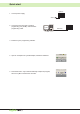
Quick start CyBro-2 1. Connect power supply. 230V~ 2. Connect the PC serial port to CyBro-2 programming port (COM1). Use RS-232C programming cable. CyPro RS-232C CyBro-2 PC 3. Install the CyPro programming software. 4. Open an example from CyPro/Examples, autodetect hardware. 5. Press Start button. CyPro will automatically compile the program, send it to CyBro-2 and start the controller.
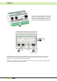
CyBro-2 CyBro-2 is a high performance programmable logic controller, featuring 230V AC or 24V DC supply voltages, digital/analog inputs/outputs, ethernet, two programmable RS-232C serial ports, high speed counter and real time clock.
Programming cable (CAD-PP-P2) 12 3 CyBro-2 RJ-9 1-TxD 2-RxD 4-GND 4 RJ-9 modular jack 4/4 PC DB-9 F 2-RxD 3-TxD 5-GND 4-DTR and 6-DSR 5 4 3 2 1 9 8 7 6 DB-9 female Pin 3 on CyBro-2 side is not connected. Pins 4 and 6 on the PC side should be connected together. COM2 cable CyBro-2 RJ-9 1-TxD 2-RxD 4-GND PC DB-9 F 2-RxD 3-TxD 5-GND CyBro-2 RJ-9 1-TxD 2-RxD 4-GND +24V 0V C3 IX0 IX1 IX2 IX3 IX4 IX5 19 20 21 22 23 24 25 26 27 ix006 ix007 inputs comm. ix008A ix009B Z analog comm.
Terminals Description power supply 230V~ (power supply 24V= version) power supply 230V~ (power supply 24V= version) not connected common for qx000-qx004 qx000 qx001 qx002 qx003 qx004 common for qx005-qx007 qx005 qx006 qx007 not connected qw000 iw000 iw001 analog common Name 230V~ (+24V=) 230V~ (0V=) C0 QX0 QX1 QX2 QX3 QX4 C1 QX5 QX6 QX7 QW0 IW0 IW1 C2 No 1 2 3 4 5 6 7 8 9 10 11 12 13 14 15 16 17 18 No Name Description 19 +24V power output 20 0V power output 21 22 23 24 25 26 27 28 29 30 31 32 33
230V outputs 24V outputs +24V 0V C3 IX0 IX1 IX2 IX3 IX4 IX5 19 20 21 1 2 230V~ L N 3 22 23 24 25 26 27 4 5 6 7 8 9 C0 QX0 QX1 QX2 QX3 QX4 +24V 0V C3 IX0 IX1 IX2 IX3 IX4 IX5 IX6 IX7 C4 IX8A IX9B Z C2 IW2 IW3 28 29 30 31 32 33 34 35 36 19 20 21 10 11 12 13 14 15 16 17 18 1 2 230V~ L N 3 C1 QX5 QX6 QX7 QW0 IW0 IW1 C2 +24V L 230V~ N 0V 22 23 24 25 26 27 4 5 6 7 8 9 C0 QX0 QX1 QX2 QX3 QX4 M IX6 IX7 C4 IX8A IX9B Z C2 IW2 IW3 28 29 30 31 32 33
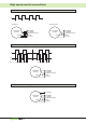
High speed counter connections A x1 (1-phase counter) A 0 1 3 2 - counting down - counting up incremental A encoder power 32 ix009B 31 ix008A 30 inputs common 20 0V 19 +24V incremental A encoder power 32 ix009B 31 ix008A 30 inputs common 20 0V 19 +24V AB x1 and AB x4 (2-phase counter) A B x1 x4 0 0 2 1 - 1 2 3 4 5 6 7 - - 1 0 - 6 5 4 3 2 1 0 incremental B A encoder power 32 ix009B 31 ix008A 30 inputs common 20 0V 19 +24V AB+Z x1 and AB+Z x4 (2-phase + zero counter) Z incremental B A enco
Galvanically isolated circuits CyBro-2-230 (230VAC) +24V 0V 19 20 CyBro-2-24 (24VDC) C IX0 IX1 IX2 IX3 IX4 IX5 IX6 IX7 C IX8A IX9B IX10Z C IW3 IW2 21 22 28 30 23 24 25 26 27 IX 29 31 32 33 34 35 IW 36 24V out 20 C IX0 IX1 IX2 IX3 IX4 IX5 IX6 IX7 C IX8A IX9B IX10Z C IW3 IW2 21 22 28 30 23 24 25 26 27 IX IEX 230V~ 3 19 29 31 32 33 34 35 IW 36 24V out CPU 1 2 230V~ L N +24V 0V 4 CPU IEX 24V= 5 6 7 8 9 C QX0 QX1 QX2 QX3 QX4 QX 10 11 12 13 C Q
IW (analog inputs) Input type Input resistance A/D converter Resolution Accuracy Scan time 0..10V or 0(4)..20 mA, selectable by DIP switches 40kohm (0..10V) 250ohm (0..20mA) SAR (succesive aproximation register), 100us conversion time 8 bits typ. 2% of FSR at 25°C 1s/100ms/10ms, software selectable QW (analog output) Output type Output current D/A converter Resolution Accuracy Scan time 0..10V max. 10mA resistor-string D~, guaranteed monotonic 8 bits typ.
IEX-2 expansions IEX-2 connecting IX6 C9 IX7 IX8 C10 IX9 IX10 C11 IX11 28 31 24 26 27 29 30 32 33 34 35 36 1 2 3 4 5 6 7 8 9 QX0 C0 QX1 QX2 C1 QX3 QX4 C2 QX5 10 11 12 13 14 15 16 17 18 QX6 C3 QX7 QX8 C4 QX9 QX10 C5 QX11 1 4 1 - GND 2 - CANL 3 - CANH 4 - +24V IEX-2 cable IEX-2 IN 23 IEX-2 OUT 4 IX4 C8 IX5 25 21 IEX-2 OUT 1 IX2 C7 IX3 22 20 IEX-2 IN 1 - +24V 2 - CANH 3 - CANL 4 - GND IX0 C6 IX1 19 CAD-SPL 11
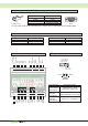
IEX-2 power supply Internal CyBro power supply has enough power for 3-4 external modules. Bigger systems should use external power supply. 1) Small system - CyBro-2-230 internal power supply Example: Bio-24R: AiR-12: AiV-12: OP-2: CyBro inputs: Bio-24 inputs: 230VAC 230V~ 160mA 50mA 50mA 40mA 8x7mA=56mA 12x7mA=84mA Total consumption: 440mA 2) Large system - CyBro-2-24 + external power supply 24VDC 230V~ 24V= Total power output for IEX-2 modules is limited to 2A because of RJ-9 connector.
Bio-24R: 12 digital inputs / 12 relay outputs Connecting example: +24V 0V 24V power supply IX0 C6 IX1 IX2 C7 IX3 IX4 C8 IX5 IX6 C9 IX7 IX8 C10 IX9 IX10 C11 IX11 19 20 21 22 23 24 25 26 27 28 29 30 31 32 33 34 35 36 1 2 3 4 5 6 7 8 9 10 11 12 13 14 15 16 17 18 QX0 C0 QX1 QX2 C1 QX3 QX4 C2 QX5 QX6 C3 QX7 QX8 C4 QX9 QX10 C5 QX11 +24V M 0V L 230V~ N 24V power supply - 24V bidirectional inputs: P-type (common plus) digital signals are connected to IX0-IX5 inputs, Nt
I/O table ix0..ix11 general error timeout_error program_error bus_error qx0..qx11 sys_req no_filter slow_filter Digital inputs. A one or more system errors occured (timeout, program or bus error). Communication failed, no messages are coming from the module. Internal or configuration error detected, module is not functional. Module detected a number of communication errors, but it is still working. Digital outputs. Set to send new filter settings to module.
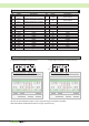
AiR-12: 12 analog RTD inputs 2-wire R6 3-wire R7 R8 R9 R10 R11 IW6 C IW7 IW8 C IW9 IW10 C IW11 10 11 12 13 14 15 16 17 18 1 2 3 4 5 6 7 8 9 IW0 C IW1 IW2 C IW3 IW4 C IW5 R0 R1 R2 R3 R4 R5 R3 R4 R5 Terminals IW6 C IW7 IW8 C IW9 IW10 C IW11 10 11 12 13 14 15 16 17 18 1 2 3 4 5 6 7 8 9 IW0 C IW1 IW2 C IW3 IW4 C IW5 R0 R1 No 1 2 3 4 5 6 7 8 9 10 11 12 13 14 15 16 17 18 Name IW0 C IW1 IW2 C IW3 IW4 C IW5 IW6 C IW7 IW8 C IW9 IW10 C IW11 Description iw000 c
Technical specifications IW (analog inputs) Number of i/o points Input type Connecton type Wire resistance A/D converter Resolution Sensor current Temperature drift Scan time Integration time Calibration reference Accuracy, scan time 12 analog inputs software selectable (common for all inputs): - Pt100/1000 (DIN751) auto selectable, measuring range -100..300°C - Ni100/1000 (DIN43760) auto selectable, measuring range -50..160°C - Ni100/1000 (Landis & Gyr) auto selectable, measuring range -50..
AiV-12: 12 analog inputs 0..10V Terminals voltage input 0..
Technical specifications Number of i/o points Input type Input resistance A/D converter Resolution Temperature drift Scan time Integration time Calibration reference Accuracy, scan time Power consumption Galvanic isolation IEX-2 baud rate Operation temperature Dimension Weight Enclosure Level of ambient pollution 12 analog inputs 0..10V 10K V/f conversion with auto calibration 13 bits (input modes with 0.1% accuracy) 11 bits (input modes with 0.5%/1% accuracy) +-0.01%/°C of measuring range 30ms..
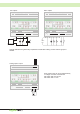
AiC-12: 12 analog inputs 0..20mA current input 0(4)..
Technical specifications Number of i/o points Input type Input resistance A/D converter Resolution Temperature drift Scan time Integration time Calibration reference Accuracy, scan time Power consumption Galvanic isolation IEX-2 baud rate Operation temperature Dimension Weight Enclosure Level of ambient pollution 12 analog inputs 0..20mA 50ohm V/f conversion with auto calibration 13 bits (input modes with 0.1% accuracy) 11 bits (input modes with 0.5%/1% accuracy) +-0.01%/°C of measuring range 30ms..
AoV-12: 12 analog outputs 0..10V V V V V V V voltage output 0..
OP-2: operator panel I/O table key_f key_e key_dn key_up general_error timeout_error program_error bus_error sys_req current_mask next_mask ir_command lcd_dimmer lcd_timeout Indicate status of operator panel F key (0-released, 1-pressed). Indicate status of operator panel E (enter) key (0-released, 1-pressed). Always zero while mask is active. Indicate status of operator panel down key (0-released, 1-pressed). Always zero while mask is active.
Common techical specifications European Union directives (CE) CyBro-2 conforms to the Electromagnetic Compatibility Directive (89/336/EEC) and Low Voltage Directive (73/23/EEC) requirements of the following standards: EN 50081-2: Electromagnetic compatibility - generic emission standard for industrial environment EN 61000-3-2 +A1 +A2: Electromagnetic compatibility - harmonic current emissions EN 61000-3-3: Electromagnetic compatibility - voltage fluctuations and flicker EN 61000-6-2: Electromagnetic compati
Power supply requirements for 24V= ITEM Nominal power supply Voltage tolerance Description 24V= 20W -15% +20% Digital inputs specifications ITEM Digital inputs ON state ON state nominal OFF state Isolation potential Logical state of input Response time Effects of incorrect input terminal connection Description type 1 either sinking or sourcing min. 15V=, 4mA 24V=, 7mA max. 5V=, 1.
Mounting CyBro-2 and all its expansions except OP-2, should be mounted vertically onto the standard DIN rail (DIN EN 50022), on a metal plate, within a suitable enclosure, like a cabinet (key or tool entry). Total power dissipation of CyBro-2 and other devices inside enclosure (cabinet) must not exceed permissible power dissipation of enclosure. CyBro-2 is designed for natural convection cooling. You must provide a clearance of at least 30 mm, both above and below the units, for proper cooling.
Wiring guidelines Follow all applicable electrical codes when wiring CyBro-2 series. Install and operate all equipment according to national and local standards. All wirings should be performed by qualified personnel. Warning Control devices may fail in an unsafe condition, resulting in unexpected operation of controlled equipment. Such unexpected action could result in death or serious personal injury, and/or equipment damage.
VIN QX 0V CyBro-2 series DC transistor outputs contain protective clamping diodes that are adequate for most applications. In case of large or frequently switched inductive loads use external suppression diodes (type 1N4001 or equivalent). You can also use diode suppression for DC loads relay switching. +24V 0V inductive load For AC loads relay switching use resistor/capacitor suppressors across either the load or the AC outputs. R > 0.
Hardware maintenance and troubleshooting Hardware maintenance There is no special maintenance procedure for CyBro family. There are no spare parts that you can change yourself. In case of malfunction, you should contact local distributor.
OP-2 drilling template - rear view 63 mm 52 mm Ř3.5 68 mm (optional rubber seal) 16 mm 17 mm 18 mm 10 mm Ř3.5 17 mm Ř3.5 Ř3.5 76.
Cybrotech Ltd, 14 Brinell Way, Harfreys Industrial Estate, Great Yarmouth, Norfolk, Nr31 OLU - UK tel: +44 (0)1157 149 991 http://www.cybrotech.co.uk info@cybrotech.co.