
Manual


HARDWARE
2-4
CPCI-824 User’s Manual
Revision 1.0, January 2006
Exceptions may be generated by the execution of instructions, or by signs from devices external to the
PPCI440GX, the internal timer facilities, debug events, or error conditions.
All interuupts, except for Machine Check, can be categorized according to two independent character-
istics of the interrupt. They are asynchronous or synchronous and critical and non-critical.
Asynchronous interrupts are caused by events that are independent of instruction execution. For
asynchronous interrupts, the address reproted to the interrupt handling routine is the address of the
instruction that would have executed next, had the asynchronous interrupt not occurred. Synchronous
interrupts are those that are caused directly by the execution (or attempted execution) of instructions.
Critical interrupt and non-critical interrupts use different save/restore register pairs. Machine check
interrupts are typically caused by some kind of hardware or storage subsystem failure, or by an attempt
to access an invalid address.
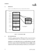
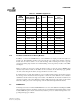
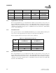
2.5.1 External Interrupts
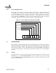
On the CPCI-824, the external interrupts are connected to the PPC440GX as shown in Table 2-2. The
local PCI interrupts are shared. Therefore, to determine which of the four local PCI interrupts caused
the interrupt, a local board register is provided at address E800 0002h.
Table 2-2. External Interrupts
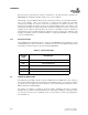
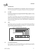
2.6 CONSOLE SERIAL PORT
The CPCI-824 adapter utilizes the first of the two UART units of the 440GX. The console serial port
with an RS-232 line interfaces has been included on the CPCI-824. The port is connected to a RJ-11
type phone jack on the adapter and can be connected to a host system using the included phone jack to
DB-25 cable (Cyclone P/N 530-2006)
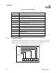
The serial port is capable of operating at speeds from 300 to 115200 bps and can be operated in
interrupt-driven or polled mode. Breeze firmware uses serial settings of 9600 bps, 8 bit data, no parity,
one stop bit, and no flow control. (9600-8N-1). The console serial port connector pin assignment is
shown in Table 2-3.
Interrupt
Input
Interrupt Type
IRQ6 TEMPERATURE INTERRUPT
IRQ7 FAN 0 INTERRUPT
IRQ8 FAN 1 INTERRUPT
IRQ9 POWER GOOD INTERRUPT
IRQ10 LOCAL PCI BUS INTERRUPT