
Manual


PRODUCT MANUALPRODUCT MANUAL
1110
UTRACK 24 REAR PANEL UTRACK 24 REAR PANEL
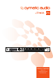
9. UTRACK 24 REAR PANEL
main out
wordclock
sync
1
out
in
2
out
in
OUTPUT
17 - 24
INPUT
17 - 24
OUTPUT
9-16
INPUT
9-16
OUTPUT
1-8
INPUT
1-8
usb
network
12vdc
uTrack
24
midi out
1
3
2
4
7
8
9
10
11
6
5
1. Option Card Slot (Not Yet Functional in version 1.0 Firmware)
The uTrack 24 can be tted with an optional 24-input, 24-output option card that provides an
alternate audio I/O path from the onboard analog I/O.
This option brings a powerful level of exibility to the uTrack 24, allowing you to:
• Expand the unit with 24 channels of digital I/O, and then use that I/O with your own A/D and
D/A converters of choice.
• Add a digital I/O format to the uTrack 24 that allows 24x24 channels of networked audio,
allowing the unit to conveniently integrate into large setups with a single cable.
For details of which specic Digital I/O Option cards will be available, please visit
www.cymaticaudio.com
2. Analog Inputs 1-24
Connect the 24 separate audio signals that you wish to record to these inputs; the 24 separate
audio signals can then be recorded to either:
• A USB drive connected to the front panel USB port
• DAW software running on a computer connected to the rear panel USB port
3. Analog Outputs 1-24
These 24 outputs carry 24 channels of audio either from:
• A multi-track audio project from a USB drive connected to the front panel USB port
• A multitrack DAW session running on a computer connected to the rear panel USB port
Both the analog inputs and outputs operate at balanced line level, +20dB, and are congured as
three separate, 8-channel, 25-pin D-subminiature connectors. The D-sub connectors are wired
to the “Tascam Standard” as shown below.
G C H G C H G C H G C H G C H G C H G C H G C H
H = HOT • C = COLD • G = GROUND
1 2 3 4 5 6 7 8
4. Main Outputs
The main outputs carry a two-channel signal that can be sourced from either:
• The stereo output of the onboard 24-channel monitor mixer. In this scenario, the main
outputs allow you to monitor a stereo mix of the 24 input or output channels, on a pair of
connected monitor speakers.
• Output channels 1-2 of your favorite DAW software. In this scenario, the main outputs allow
you to monitor a stereo mix of your DAW session, when using the uTrack 24 as a computer
audio interface in a recording studio.
The main outputs are balanced ¼” tip-ring-sleeve (TRS) connectors, operating at +4dB.
5. Word Clock Input
The uTrack 24 can be “slaved” to an external word clock signal by connecting it to the BNC word
clock input. This allows the uTrack 24 to be properly integrated into a larger complement of digital
audio equipment, where the clock signals of all connected equipment need to be synchronized.
Adjust the uTrack 24’s “Wordclock” menu to congure it to slave to an incoming external clock, as
opposed to running on its own internal clock. The settings bar at the top of the LCD screen will
indicate whether the uTrack 24 is using an internal or external clock signal.
6. Word Clock Output
This connector outputs a standard digital word clock signal, running at the sample rate that the
uTrack 24 is currently set to. The word clock output is useful when you want to use the uTrack 24
as a “clock master” and wish to slave other digital equipment to its internal clock signal.
7. Synchronization Input/Output Connectors (Not Yet Functional in version 1.0 Firmware)
These are used to synchronize multiple uTrack 24 units into a larger, 48-track recording system.
The synchronization function is not yet activated in the uTrack 24 1.0 rmware.
8. MIDI Output Connector: (Available in future rmware update)
The MIDI output connector outputs MIDI data from a SMF (Standard MIDI File) that resides in the
same folder as a project’s audio les.
This allows the uTrack 24 to output MIDI data to a software synthesizer, MIDI controlled lighting
system, effects switching system, etc., synchronized and in time with audio data that is played out
of the uTrack 24’s audio outputs.
9. USB Connector
The rear panel USB computer connects to the USB port of a Windows or OS X computer, as well
as to the USB port of an iPad camera connection accessory. Upon doing so, the uTrack 24 acts
as a 24-input, 24-output computer audio interface.
The ability to record 24 separate audio inputs to your favorite DAW allows you to record a large
musical ensemble while still keeping each player and instrument separated, for maximum
exibility.
The 24 separate outputs allow for great exibility in routing outputs from a DAW session, such
as sending many separate headphone mixes to an external headphone amplier, or sending 24
separate channels of audio to an external analog mixer, for “mixing out of the box”.
10. Network Connector
This RJ-45 connector allows connection of the uTrack 24 to a standard Ethernet network. In the
current rmware version the network connection can be used to update the uTrack 24’s rmware.
Future rmware updates will allow for the uTrack’s recording, playback, and mastering functions
to be controlled by computer and/or tablet software, running on a device connected to the same
network.
11. Power Connector
Connect the included external power supply to this connector. Do not connect any other power
supply except the one that was supplied with your uTrack 24.
Note that the uTrack 24 does not contain an “on/off” power switch; this is by design, as it reduces
the possibility of accidentally shutting down the unit during a critical recording from pressing a
power switch. As long as the power supply connector is attached and connected to a wall-power
source, the uTrack 24 will always be powered on.