CMIR-44 4 by 4 Infrared Matrix Operation Manual CMIR-44
Safety Precautions Please read all instructions before attempting to unpack or install or operate this equipment, and before connecting the power supply. Please keep the following in mind as you unpack and install this equipment: Always follow basic safety precautions to reduce the risk of fire, electrical shock and injury to persons. To prevent fire or shock hazard, do not expose the unit to rain, moisture or install this product near water.
Table of Contents 1. Introduction…………………………………………………........………. 1 2. Applications……………………..…………………………................…. 1 3. Package Contents…………………………......…………….............… 1 4. System Requirements……...…………………..….…………........……. 1 5. Features…………………………………………….......……........……… 1 6. Specifications..………………………………………...........………...…. 2 7. Hardware Description………………...……........….....................…… 7.1 Front Panel ...................................................................
1. Introduction The Infrared 4 by 4 Matrix box is design to control the source equipments from display/receiver side. Users can use exiting source’s remote controls to control DVD player, VCR, satellite and etc…anywhere in the distance range. With cross matrix design and a main total control this device allows user with maximum control ability for their infrared sending.
6. Specifications IR Frequency 20KHz to 70KHz Input port 4 x independent IR Blasters; 1 x total IR blaster control Output port 4 x independent IR Receiver; 1 x total IR receiver control Power Supply 5VDC/1A (US/EU standards, CE/FCC/UL certified) ESD Protection Human body model: ± 8kV (air-gap discharge) ± 4kV (contact discharge) Dimensions (mm) 180(W) x 124(D) x 25(H) Weight(g) 450 Chassis Material Aluminum Silkscreen Color Silver Power Consumption 0.
7. Hardware Description The following sections describe the hardware components of the unit. 7.1 Front Panel 1 2 3 4 5 6 ① IR sensor: To control the system itself. ② POWER Button & LED: Press to turn on or set it to standby. When system is ON the LED will illuminate in GREEN color. Press again to enter into STANDBY mode, the LED will illuminate in RED color. ③ IR IN 1 & output LED: Press the button to select which output IR signal is to send and the LED will illuminate according to the selection.
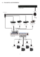
.2 Rear panel 1 2 3 4 5 ① IR OUT ALL: This slot is where you connect the IR blaster cable included in the package. Place it in the distance that all sources and device are able to receive the infrared signal. ② IR OUT A~D: These slots are where you connect with IR blaster cables included in the package. Place it in the distance that only the designated source equipment is able to receive the infrared signal. ③ IR IN ALL: This slot is where you connect the IR receiver cable included in the package.
. IR Cable Pin Definitions 8.1 IR Receiver IR Receiver ① IR signal ② Power 5V ③ Grounding ① ②③ 8.2 IR Blaster IR Blaster ① Power 5V ② NC ③ IR blaster signal ① ②③ Note: The frequency on both IR Receiver & Blaster can support 20~70KHz. 8.
. Remote Control 1. Power: Press the button to turn on/ Standby the unit. 2. IR IN 1 Select for IR OUT A~D: Press A, B, C or D to select the desired output IR signal sending. 3. IR IN 2 Select for IR OUT A~D: Press A, B, C or D to select the desired output IR signal sending. 4. IR IN 3 Select for IR OUT A~D: Press A, B, C or D to select the desired output IR signal sending. 5. IR IN 4 Select for IR OUT A~D: Press A, B, C or D to select the desired output IR signal sending.
6.
Acronyms Acronym Complete Term IR Infrared A 20100204 MPM-CMIR44