
User's Guide

RN2903
DS00000A-page 8 Advance Information 2015 Microchip Technology Inc.
3.0 TYPICAL HARDWARE CONNECTIONS
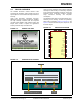
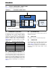
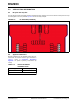
Figure 3-1 shows the typical hardware connections.
FIGURE 3-1: HARDWARE CONNECTIONS
3.1 INTERFACE TO HOST MCU
The RN2903 module has a dedicated UART interface
to communicate with a host controller. Optional
handshake lines are supported in future firmware
releases. The “RN2903 LoRa™ Technology Module
Command Reference User’s Guide” (DS40000000A)
provides a detailed UART command description.
Table 3-1 shows the default settings for the UART
communication.
3.2 GPIO PINS (GPIO1–GPIO14)
The module has 14 GPIO pins. These lines can be
connected to switches, LEDs, and relay outputs. The
pins are either logic inputs or outputs that can be
accessed via the module firmware. These pins have
limited sink and source capabilities. The current
firmware release only supports output function on all
GPIOs. Electrical characteristics are described in
Table 2-2.
3.3 RF CONNECTION
When routing RF path, use proper strip lines with an
impedance of 50 Ohm.
3.4 RESET PIN
The module’s reset pin is an active-low logic input.
3.5 POWER PINS
It is recommended to connect power pins (Pin 12 and
34) to a stable supply voltage with sufficient source
current. Table 2-2 shows the current consumption.
Additional filtering capacitors are not required but can
be used to ensure stable supply voltage in noisy
environment.
RN2903
GPIOsHost MCU
TX
TXRX
RX
CTS
(1)
RTS
RTS
(1)
CTS
RFH
915 MHz band
UART
Status LEDs,
switches,
logic IOs,
etc.
14
Note 1: Optional handshake lines are supported in future firmware releases.
TABLE 3-1: DEFAULT UART SETTINGS
Specification Description
Baud Rate 57600 bps
Packet Length 8 bit
Parity Bit No
Stop Bits 1 bit
Hardware Flow Control No