
Specifications


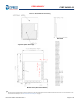


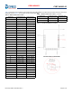


Table Of Contents
- CYBT-243053-02, EZ-BT™ Module
- General Description
- Benefits
- More Information
- Overview
- Pad Connection Interface
- Recommended Host PCB Layout
- Module Connections
- Connections and Optional External Components
- Critical Components List
- Antenna Design
- Bluetooth Baseband Core
- Power Management Unit
- Integrated Radio Transceiver
- Microcontroller Unit
- Peripherals and Communication Interfaces
- Electrical Characteristics
- Chipset RF Specifications
- Timing and AC Characteristics
- Environmental Specifications
- Regulatory Information
- Packaging
- Ordering Information
- Acronyms
- Document Conventions
- Document History Page
- Sales, Solutions, and Legal Information

Document Number: 002-28015 Rev. ** Page 10 of 42
PRELIMINARY
CYBT-243053-02
Table 5 details the available Input and Output functions that are configurable to any solder pad in Tab le that are marked as SuperMux
capable.
Table 5. GPIO SuperMux Input and Output Functions
Function Input or Output Function Type
GPIOs
Required
Function Connection Description
SPI 1 Input/Output
Serial Communication
(Master or Slave)
4 ~ 7
SPI 1 Clock
SPI 1 Chip Select
SPI 1 MOSI
SPI 1 MISO
SPI 1 I/O 2 (Quad SPI)
SPI 1 I/O 3 (Quad SPI)
SPI 1 Interrupt
SPI 2 Input/Output
Serial Communication
(Master or Slave)
4 ~ 7
SPI 2 Clock
SPI 2 Chip Select
SPI 2 MOSI
SPI 2 MISO
SPI 2 I/O 2 (Quad SPI)
SPI 2 I/O 3 (Quad SPI)
SPI 2 Interrupt
PUART
Input Serial Communication Input
4
Peripheral UART RX
Peripheral UART CTS
Output Serial Communication Output
Peripheral UART TX
Peripheral UART RTS
I
2
C Input/Output
Serial Communication
(Master or Slave)
2
I2C Clock
I2C Data
PCM In Input Audio Input Communication 3
PCM Input
PCM Clock
PCM Sync
PCM Out Output
Audio Output
Communication
3
PCM Output
PCM Clock
PCM Sync
I
2
S In Input Audio Input Communication 3
I2S DI, Data Input
I2S WS, Word Select
I2S Clock
I
2
S Out Output
Audio Output
Communication
3
I2S DO, Data Output
I2S WS, Word Select
I2S Clock
PDM Input Microphone 1 ~ 2
PDM Input Channel 1
PDM Input Channel 2
PWM Output Pulse Width Modulator 1 ~ 6
PWM Channel 0
PWM Channel 1
PWM Channel 2
PWM Channel 3
PWM Channel 4
PWM Channel 5