
Specifications


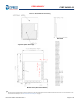


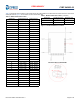


Table Of Contents
- CYBT-243053-02, EZ-BT™ Module
- General Description
- Benefits
- More Information
- Overview
- Pad Connection Interface
- Recommended Host PCB Layout
- Module Connections
- Connections and Optional External Components
- Critical Components List
- Antenna Design
- Bluetooth Baseband Core
- Power Management Unit
- Integrated Radio Transceiver
- Microcontroller Unit
- Peripherals and Communication Interfaces
- Electrical Characteristics
- Chipset RF Specifications
- Timing and AC Characteristics
- Environmental Specifications
- Regulatory Information
- Packaging
- Ordering Information
- Acronyms
- Document Conventions
- Document History Page
- Sales, Solutions, and Legal Information

Document Number: 002-28015 Rev. ** Page 9 of 42
PRELIMINARY
CYBT-243053-02
Module Connections
Table 4 details the solder pad connection definitions and available functions for each connection pad. The GPIO connections available
on the CYBT-243053-02 can be configured to any of the input or output functions listed in Table 5. Table 4 specifies any function that
is required to be used on a specific solder pad, and also identifies SuperMux capable GPIOs that can be configured using the
ModusToolbox device configurator.
Table 4. CYBT-243053-02 Solder Pad Connection Definitions
Pad Pad Name Silicon Pin Name XTALI/O ADC GPIO SuperMux Capable
[2]
GroundGNDGND1
Power Supply Input (2.6V ~ 3.63V)VDDIOVDD2
External Reset (Active Low)RST_NXRES3
IN10-P29P294 ✓✓ see Table
IN7-P32P325 ✓✓ see Table
--P27P276 ✓✓ see Table
IN2-P37P377 ✓✓ see Table
IN11-P28P288 ✓✓ see Table
IN29-P0P09 ✓✓ see Table
IN28-P1P110 ✓✓ see Table
IN25-P10P1011 ✓✓ see Table
IN22-P13P1312 ✓✓ see Table
GroundGNDGND13
IN23-P12P1214 ✓✓ see Table
IN24-P11P1115 ✓✓ see Table
IN26-P9P916 ✓✓ see Table
IN21-P14P1417 ✓✓ see Table
IN18-P17P1718 ✓✓ , see Table
--P5P519 ✓✓ see Table
--P6P620 ✓✓ see Table
--P4P421 ✓✓ see Table
--P2P222 ✓✓ see Table
--P3P323 ✓✓ see Table
XTALI_32KXTALI_32K24
External Oscillator Input
(32KHz)
---
XTALO_32KXTALO_32K25
External Oscillator
Output (32KHz)
---
IN20-P15P1526 ✓✓ see Table
IN27-P8P827 ✓✓ see Table
UART (HCI UART) Clear To Send Input OnlyUART_CTS_NUART_CTS_N28
UART (HCI UART) Request To Send Output OnUART_RTS_NUART_RTS_N29 ly
UART (HCI UART) Transmit Data OnlyUART_TXDUART_TXD30
UART (HCI UART) Receive Data OnlyUART_RXDUART_RXD31
HOST_WAKEHOST_WAKE32
A signal from the CYBT-243043-02
module to the host indicating
that the Bluetooth device requires
attention.
DEV_WAKEDEV_WAKE33
A signal from the host to the CYBT-243043-02 module indicating
that the host requires attention.
--P26P2634 ✓✓ see Table
GroundGNDGND35
Note
2. The CYBT-243053-02 can configure GPIO connections to any Input/Output function described in Tab le using the ModusToolbox Device Configurator.