
Specifications


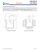

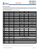
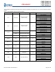
Table Of Contents
- CYBT-273063-02, CYBT-263064-02, CYBT-263065-02, EZ-BT™ Module
- General Description
- Benefits
- More Information
- Contents
- Overview
- Pad Connection Interface
- Recommended Host PCB Layout
- Module Connections
- Connections and Optional External Components
- Critical Components List
- Antenna Design
- Qualified Antenna for CYBT-263064-02 and CYBT-263065-02
- Bluetooth Baseband Core
- Power Management Unit
- Integrated Radio Transceiver
- Microcontroller Unit
- Peripherals and Communication Interfaces
- Electrical Characteristics
- Chipset RF Specifications
- Timing and AC Characteristics
- Environmental Specifications
- Regulatory Information
- Packaging
- Ordering Information
- Acronyms
- Document Conventions
- Document History Page
- Sales, Solutions, and Legal Information

Document Number: 002-29354 Rev. ** Page 10 of 45
PRELIMINARY
CYBT-273063-02
CYBT-263064-02
CYBT-263065-02
Table 5 details the available Input and Output functions that are configurable to any solder pad in Table 4 that are marked as SuperMux
capable.
Table 5. GPIO SuperMux Input and Output Functions
Function Input or Output Function Type GPIOs Required Function Connection Description
SPI 1 Input/Output
Serial Communication
(Master or Slave)
4 ~ 7
SPI 1 Clock
SPI 1 Chip Select
SPI 1 MOSI
SPI 1 MISO
SPI 1 I/O 2 (Quad SPI)
SPI 1 I/O 3 (Quad SPI)
SPI 1 Interrupt
SPI 2 Input/Output
Serial Communication
(Master or Slave)
4 ~ 7
SPI 2 Clock
SPI 2 Chip Select
SPI 2 MOSI
SPI 2 MISO
SPI 2 I/O 2 (Quad SPI)
SPI 2 I/O 3 (Quad SPI)
SPI 2 Interrupt
PUART
Input Serial Communication Input
4
Peripheral UART RX
Peripheral UART CTS
Output Serial Communication Output
Peripheral UART TX
Peripheral UART RTS
I
2
C Input/Output
Serial Communication
(Master or Slave)
2
I2C Clock
I2C Data
PCM In Input Audio Input Communication 3
PCM Input
PCM Clock
PCM Sync
PCM Out Output Audio Output Communication 3
PCM Output
PCM Clock
PCM Sync
I
2
S In Input Audio Input Communication 3
I2S DI, Data Input
I2S WS, Word Select
I2S Clock
I
2
S Out Output Audio Output Communication 3
I2S DO, Data Output
I2S WS, Word Select
I2S Clock
PDM Input Microphone 1 ~ 2
PDM Input Channel 1
PDM Input Channel 2
PWM Output Pulse Width Modulator 1 ~ 6
PWM Channel 0
PWM Channel 1
PWM Channel 2
PWM Channel 3
PWM Channel 4
PWM Channel 5