
Specifications


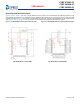

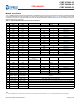
Table Of Contents
- CYBT-273063-02, CYBT-263064-02, CYBT-263065-02, EZ-BT™ Module
- General Description
- Benefits
- More Information
- Contents
- Overview
- Pad Connection Interface
- Recommended Host PCB Layout
- Module Connections
- Connections and Optional External Components
- Critical Components List
- Antenna Design
- Qualified Antenna for CYBT-263064-02 and CYBT-263065-02
- Bluetooth Baseband Core
- Power Management Unit
- Integrated Radio Transceiver
- Microcontroller Unit
- Peripherals and Communication Interfaces
- Electrical Characteristics
- Chipset RF Specifications
- Timing and AC Characteristics
- Environmental Specifications
- Regulatory Information
- Packaging
- Ordering Information
- Acronyms
- Document Conventions
- Document History Page
- Sales, Solutions, and Legal Information

Document Number: 002-29354 Rev. ** Page 8 of 45
PRELIMINARY
CYBT-273063-02
CYBT-263064-02
CYBT-263065-02
Table 3 provides the center location for each solder pad on the CYBT-2X30XX-02. All dimensions are referenced to the center of the
solder pad. Refer to Figure 7 for the location of each module solder pad.
Table 3. Module Solder Pad Location Figure 7. Solder Pad Reference Location
Solder Pad
(Center of Pad)
Location (X,Y) from
Orign (mm)
Dimension from
Orign (mils)
1 (0.33, 6.83) (12.99, 268.90)
2 (0.33, 7.80) (12.99, 307.09)
3 (0.33, 8.76) (12.99, 344.88)
4 (0.33, 9.73) (12.99, 383.07)
5 (0.33, 10.69) (12.99, 420.87)
6 (0.33, 11.66) (12.99, 459.05)
7 (0.33, 12.62) (12.99, 496.85)
8 (0.33, 13.59) (12.99, 535.04)
9 (0.33, 14.55) (12.99, 572.83)
10 (0.33, 15.52) (12.99, 611.02)
11 (0.33, 16.48) (12.99, 648.82)
12 (0.33, 17.45) (12.99, 687.01)
13 (1.42, 18.67) (55.91, 735.04)
14 (2.39, 18.67) (94.09, 735.04)
15 (3.35, 18.67) (131.89, 735.04)
16
(4.32, 18.67) (170.08, 735.04)
17 (5.28, 18.67) (207.87, 735.04)
18 (6.25, 18.67) (246.06, 735.04)
19 (7.22, 18.67) (284.25, 735.04)
20 (8.18, 18.67) (322.05, 735.04)
21 (9.15, 18.67) (360.24, 735.04)
22 (10.11, 18.67) (398.03, 735.04)
23 (11.08, 18.67) (436.22, 735.04)
24 (12.17, 17.45) (479.13, 687.01)
25 (12.17, 16.48) (479.13, 648.82)
26 (12.17, 15.52) (479.13, 611.02)
27 (12.17, 14.55) (479.13, 572.83)
28 (12.17, 13.59) (479.13, 535.04)
29 (12.17, 12.62) (479.13, 496.85)
30 (12.17, 11.66) (479.13, 459.05)
31 (12.17, 10.69) (479.13, 420.87)
32 (12.17, 9.73) (479.13, 383.07)
33 (12.17, 8.76) (479.13, 344.88)
34 (12.17, 7.80) (479.13, 307.09)
35 (12.17, 6.83) (479.13, 268.90)
Top View (Seen on Host PCB)