
Data Sheet


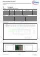
Table Of Contents
- General description
- Module description
- Power consumption
- Functional capabilities
- Benefits
- More information
- References
- Development environments
- Technical support
- Contents
- 1 Overview
- 2 Pad connection interface
- 3 Recommended host PCB layout
- 4 Module connections
- 5 Connections and optional external components
- 6 Functional description
- 7 Integrated radio transceiver
- 8 Peripheral and communication interfaces
- 9 Keyboard scanner
- 10 Clock frequencies
- 11 GPIO port
- 12 PWM
- 13 Power management unit
- 14 Electrical characteristics
- 15 Chipset RF specifications
- 16 Timing and AC characteristics
- 17 Environmental specifications
- 18 Regulatory information
- 19 Packaging
- 20 Ordering information
- 21 Acronyms
- 22 Document conventions
- Revision History

Preliminary Datasheet 41 of 58 002-33419 Rev. **
2021-07-22
AIROC™ Bluetooth® LE module
Timing and AC characteristics
16.3 I
2
C interface timing
Figure 16 I
2
C Interface timing diagram
Table 21 I
2
C Interface Timing Specifications
Reference Characteristics Min Max Unit
1
Clock frequency –
100
kHz
400
800
1000
2
START condition setup time 650 –
ns
3
START condition hold time 280 –
4
Clock low time 650 –
5
Clock high time 280 –
6
Data input hold time
[16]
0 –
7
Data input setup time 100 –
8
STOP condition setup time 280 –
9
Output valid from clock – 400
10
Bus free time
[17]
650 –
Notes
16.As a transmitter, 125 ns of delay is provided to bridge the undefined region of the falling edge of SCL to avoid
unintended generation of START or STOP conditions.
17.Time that the bus must be free before a new transaction can start.