
Data Sheet


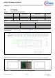
Table Of Contents
- General description
- Module description
- Power consumption
- Functional capabilities
- Benefits
- More information
- References
- Development environments
- Technical support
- Contents
- 1 Overview
- 2 Pad connection interface
- 3 Recommended host PCB layout
- 4 Module connections
- 5 Connections and optional external components
- 6 Functional description
- 7 Integrated radio transceiver
- 8 Peripheral and communication interfaces
- 9 Keyboard scanner
- 10 Clock frequencies
- 11 GPIO port
- 12 PWM
- 13 Power management unit
- 14 Electrical characteristics
- 15 Chipset RF specifications
- 16 Timing and AC characteristics
- 17 Environmental specifications
- 18 Regulatory information
- 19 Packaging
- 20 Ordering information
- 21 Acronyms
- 22 Document conventions
- Revision History

Preliminary Datasheet 42 of 58 002-33419 Rev. **
2021-07-22
AIROC™ Bluetooth® LE module
Timing and AC characteristics
Note The time periods specified in Figure 17 and Figure 18 are defined by the transmitter speed. The receiver
specifications must match transmitter performance.
Table 22 Timing for I
2
S transmitters and receivers
Transmitter Receiver
NotesLower limit Upper limit Lower limit Upper limit
MinMaxMinMaxMinMaxMinMax
Clock Period T T
tr
–––T
r
–––18
Master mode: Clock generated by transmitter or receiver
HIGH t
HC
0.35T
tr
– – – 0.35T
tr
–––19
LOWt
LC
0.35T
tr
– – – 0.35T
tr
–––19
Slave mode: Clock accepted by transmitter or receiver
HIGH t
HC
–0.35T
tr
–––0.35T
tr
––20
LOW t
LC
–0.35T
tr
–––0.35T
tr
––20
Rise time t
RC
––0.15T
tr
––– –21
Transmitter
Delay t
dtr
–––0.8T––––22
Hold time t
htr
0–––––––21
Receiver
Setup time t
sr
–––––0.2T
r
––23
Hold time t
hr
–––––0––22
Notes
18.The system clock period T must be greater than T
tr
and T
r
because both the transmitter and receiver have
to be able to handle the data transfer rate.
19.At all data rates in master mode, the transmitter or receiver generates a clock signal with a fixed mark/space
ratio. For this reason, t
HC
and t
LC
are specified with respect to T.
20.In slave mode, the transmitter and receiver need a clock signal with minimum HIGH and LOW periods so that
they can detect the signal. So long as the minimum periods are greater than 0.35T
r
, any clock that meets the
requirements can be used.
21.Because the delay (t
dtr
) and the maximum transmitter speed (defined by T
tr
) are related, a fast transmitter
driven by a slow clock edge can result in t
dtr
not exceeding t
RC
which means t
htr
becomes zero or negative.
Therefore, the transmitter has to guarantee that t
htr
is greater than or equal to zero, so long as the clock
rise-time t
RC
is not more than t
RCmax
, where t
RCmax
is not less than 0.15T
tr
.
22.To allow data to be clocked out on a falling edge, the delay is specified with respect to the rising edge of the
clock signal and T, always giving the receiver sufficient setup time.
23.The data setup and hold time must not be less than the specified receiver setup and hold time.