
User's Manual
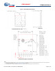
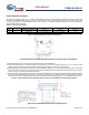
Table Of Contents
- General Description
- Benefits
- Overview
- Pad Connection Interface
- Recommended Host PCB Layout
- Module Connections
- Bluetooth Baseband Core
- Power Management Unit
- Microprocessor Unit
- Integrated Radio Transceiver
- Peripheral Transport Unit
- ADC Port
- PWM
- Triac Control
- Security Engine
- Electrical Characteristics
- RF Specifications
- Timing and AC Characteristics
- Environmental Specifications
- Regulatory Information
- Packaging
- Ordering Information
- Acronyms
- Document Conventions
- Document History Page
- Sales, Solutions, and Legal Information

Document Number: 002-19043 Rev. PRELIMINARY Page 4 of 33
PRELIMINARY
CYBLE-413136-01
Figure 2. Module Mechanical Drawing
Bottom View (Seen from Bottom)
Side View
Top View (See from Top)
Notes
4. No metal should be located beneath or above the antenna area. Only bare PCB material should be located beneath the antenna area. For more information on
recommended host PCB layout, see “Recommended Host PCB Layout” on page 6.
5. The CYBLE-413136-01 includes castellated pad connections, denoted as the circular openings at the pad location above.