
User's Manual
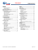
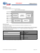
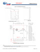
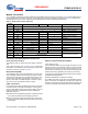
Table Of Contents
- General Description
- Benefits
- Overview
- Pad Connection Interface
- Recommended Host PCB Layout
- Module Connections
- Bluetooth Baseband Core
- Power Management Unit
- Microprocessor Unit
- Integrated Radio Transceiver
- Peripheral Transport Unit
- ADC Port
- PWM
- Triac Control
- Security Engine
- Electrical Characteristics
- RF Specifications
- Timing and AC Characteristics
- Environmental Specifications
- Regulatory Information
- Packaging
- Ordering Information
- Acronyms
- Document Conventions
- Document History Page
- Sales, Solutions, and Legal Information

Document Number: 002-19043 Rev. PRELIMINARY Page 7 of 33
PRELIMINARY
CYBLE-413136-01
Module Connections
Tab le 3 details the solder pad connection definitions and available functions for each connection pad. Table 3 lists the solder pads on
the CYBLE-413136-01, the silicon device pin, and denotes what functions are available for each solder pad. Ta ble 3 also lists the
primary/intended function for each solder pad for the application this module was specifically designed for.
Connections and Optional External Components
Power Connections (VCC)
The CYBLE-413136-01 contains one power supply connection,
VCC.
VCC accepts a supply input of 3.30 V. Table 9 provides this
specification. The maximum power supply ripple for this power
connection is 100 mV, as shown in Table 9.
External Reset (XRES)
The CYBLE-413136-01 has an integrated power-on reset circuit
which completely resets all circuits to a known power on state.
This action can also be driven by an external reset signal, which
can be used to externally control the device, forcing it into a
power-on reset state. The XRES signal is an active-low signal,
which is an input to the CYBLE-413136-01 module.
UART Connections
For full UART functionality, all UART signals must be connected
to the Host device. If full UART functionality is not being used,
and only UART RXD and TXD are desired or capable, then the
following connection considerations should be followed for
UART RTS and CTS:
n UART RTS: Can be left floating, pulled low, or pulled high. RTS
is not critical for initial firmware uploading at power on.
n UART CTS: Must by pulled low to bypass flow control and to
ensure that continuous data transfers are made from the host
to the module.
External Component Recommendation
Power Supply Circuitry
It is not required to place any power supply decoupling or noise
reduction circuitry on the host PCB. If desired, an external ferrite
bead between the supply and the module connection can be
included, but is not necessary. If used, the ferrite bead should be
positioned as close as possible to the module pin connection.
If used, the recommended ferrite bead value is 330Ω, 100 MHz.
(Murata BLM21PG331SN1D).
Apple MFi Authentication Coprocessor Interface
The CYBLE-413136-01 comes with an integrated MFi authenti-
cation co-processor. No additoinal connections are required to
be made to the module to enable Apple HomeKit functionality. All
connections required are internally routed on the module PCB.
Table 3. Solder Pad Connection Definitions
Pad Num-
ber
Pad Name UART PWM GPIO Primary Function
1 VCC Power Supply Input (3.30V) Power Supply Input
2 GND Ground Connection Ground Connection
3PWM1 33PWM R, G, B, or W Function
4PWM2 33PWM R, G, B, or W Function
5PWM3 33PWM R, G, B, or W Function
6PWM4 33PWM R, G, B, or W Function
7ADC ADC Input
8PUART_TX 3(UART_TXD) Peripheral UART TXD
9PUART_RX 3(UART_RXD) Peripheral UART RXD
10 XRES External Reset Hardware Connection Input External Reset (Active Low)
11 UART_RXD 3(UART_RXD) UART RXD
12 UART_TXD 3(UART_TXD) UART TXD
13 UART_CTS 3(UART_CTS) UART CTS
14 UART_RTS 3(UART_RTS) UART RTS
GND GND Ground Connection
Ground Connections
Must be soldered to host board
GND GND Ground Connection