
User's Manual
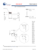
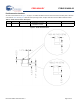
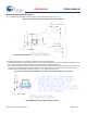

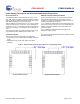
Table Of Contents
- General Description
- Contents
- Overview
- Pad Connection Interface
- Recommended Host PCB Layout
- Power Supply Connections and Recommended External Components
- Electrical Specification
- Environmental Specifications
- Regulatory Information
- Ordering Information
- Acronyms
- Document Conventions
- Errata
- Document History Page
- Sales, Solutions, and Legal Information

PRELIMINARY
CYBLE-214009-00
Document Number: 002-09714 Rev. ** Page 6 of 40
Recommended Host PCB Layout
Figure 3 details the recommended PCB layout pattern for the host PCB. Dimensions are in mm.
Figure 3. Recommended PCB Layout Pattern for CYBLE-214009-00
To maximize RF performance, the host layout should follow these recommendations:
1. The ideal placement of the Cypress BLE module is in a corner of the host board with the antenna located on the edge of the host
board. This placement minimizes the additional recommended keep-out area stated in item 2.
2. It is recommended that the area around the Cypress BLE module trace antenna should contain an additional keep-out area, where
no grounding or signal traces are contained. The keep-out area applies to all layers of the host board. The recommended
dimensions of the host PCB keep-out area are shown in Figure 4 (dimensions are in mm).
Figure 4. Recommended Host PCB Keep-Out Area Around the CYBLE-214009-00 Trace Antenna
Top View (On Host PCB)
Host PCB Keep-Out Area Around Trace Antenna