
Specifications
found in the example called a Usage Page. The reason for the Usage Page is that it is necessary to allow for more than 256
possible Usage tags. Usage Page tags are used as a second byte which allows for up to 65536 Usages.
Logical Minimum and Logical Maximum are used to bound the values that a device will return. For example, a keyboard that
will return the values 0 to 101 for the scan code of each key press will have a Logical Minimum (0) and Logical Maximum
(101). These are different from Physical Minimum and Physical Maximum. Physical boundaries give some meaning to the
Logical boundaries. For example, a thermometer may have Logical boundaries of 0 to 999, but the Physical boundaries may
be 32 to 212. In other words, the boundaries on the thermometer are 32 to 212 degrees Fahrenheit, but there are one
thousand steps defined between the boundaries.
Report Size and Report Count define the structures that the data will be transferred in. Report Size gives the size of the
structure in bits. Report Count defines how many structures will be used. In the example descriptor above, the lines Report
Size (8) and Report Count (6) define a 6 byte key array for a keyboard.
Collection items are used to show a relationship between two or more sets of data. For example, a minimal keyboard can be
described as a collection of four data items (Modifier byte, Reserved byte, LED report, and Key Array). End Collection items
simply close the collection.
It is important to note that all examples given here are merely for clarification. They are not necessarily definitive solutions.
A more detailed description of all items discussed here as well as other descriptor issues can be found in the “Device Class
Definition for Human Interface Devices (HID)” revision 1.0 and in the “Universal Serial Bus Specification” revision 1.0,
chapter 9. Both of these documents can be found on the USB world wide web site at http://www.usb.org/.
Functionality
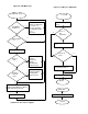
Main Loop
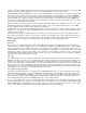
The main loop of the firmware (Figure 20) waits for the keyboard Scan Task to be scheduled by the 1 ms ISR (Figure 21),
and then executes it. At the completion of the scan task, the main loop will check for global scanning errors, such as rollover
errors or phantom-key errors, and will format an error report if either of these conditions are present (this report consists of a
standard key report in which all 6 key array positions in the End Point 1 FIFO (bytes 2–7) will be loaded with usage code
01h). Reports, either key reports or error reports, are sent to the host via End Point 1 any time a report is requested. The
host side software will repeat the key press until the release of the key, so that the device does not require a continuous
report when no key status changes have occurred.
Scan Task
The USB Scan Task consists of a call to usb_scan_keys. This routine first calls the generic matrix scanning routine, which
maintains an image of the state of the key matrix since the last time the routine was invoked. The matrix scanning routine
compares the current state of the keys against the image by sequencing through the rows and columns of the matrix. As
successive key state changes are detected, they are saved as the “current” state in the image, and are also reported to the
USB scan-conversion code via a subroutine call, with a generic key-code and state-change (up or down) as arguments. The
scan-conversion code converts this generic key information into the appropriate USB usage codes, and places it in a USB-
formatted buffer (discussed above) for eventual transmission to the host.
Suspend/Resume/Remote Wakeup
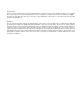
According to the USB Specification 1.0, a device has to go into suspend mode after 3 ms of no bus activity. The 1 ms ISR
determines when this condition occurs (by reading the Bus Activity bit, bit 3, of the USB Status and Control Register, 1Fh)
and sets the SUSPEND_FLAG accordingly. The main loop, upon detecting the assertion of this flag, suspends the
microcontroller by setting bit 0 (the Run bit) and bit 3 (Suspend bit) of the Processor Status and Control Register (FFh). The
microcontroller will resume operation if a GPIO interrupt occurs or bus activity resumes.
Prior to suspending the microcontroller, the firmware pulls down all the column port lines and enables a falling edge interrupt
on all Port 2 lines (Row port). If any key is pressed while in the suspended state, one of the row lines will be pulled low and
trigger a GPIO interrupt. The GPIO ISR causes the microcontroller to return from suspend mode, and send a resume signal
(force a K state where D+ is high and D- is low for 10ms) to wake up the host (remote wake up).