
User`s guide

CY7C63722C
CY7C63723C
CY7C63743C
FOR
FOR
Document #: 38-08022 Rev. *C Page 13 of 49
11.0 Suspend Mode
The CY7C637xxC parts support a versatile low-power
suspend mode. In suspend mode, only an enabled interrupt or
a LOW state on the D–/SDATA pin will wake the part. Two
options are available. For lowest power, all internal circuits can
be disabled, so only an external event will resume operation.
Alternatively, a low-power internal wake-up timer can be used
to trigger the wake-up interrupt. This timer is described in
Section 11.2, and can be used to periodically poll the system
to check for changes, such as looking for movement in a
mouse, while maintaining a low average power.
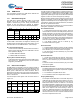
The CY7C637xxC is placed into a low-power state by setting
the Suspend bit of the Processor Status and Control Register
(Figure 20-1). All logic blocks in the device are turned off
except the GPIO interrupt logic, the D–/SDATA pin input
receiver, and (optionally) the wake-up timer. The clock oscil-
lators, as well as the free-running and Watchdog timers are
shut down. Only the occurrence of an enabled GPIO interrupt,
wake-up interrupt, SPI slave interrupt, or a LOW state on the
D–/SDATA pin will wake the part from suspend (D– LOW
indicates non-idle USB activity). Once one of these resuming
conditions occurs, clocks will be restarted and the device
returns to full operation after the oscillator is stable and the
selected delay period expires. This delay period is determined
by selection of internal vs. external clock, and by the state of
the Ext. Clock Resume Delay as explained in Section 9.0.
In suspend mode, any enabled and pending interrupt will wake
the part up. The state of the Interrupt Enable Sense bit (Bit 2,
Figure 20-1) does not have any effect. As a result, any inter-
rupts not intended for waking from suspend should be disabled
through the Global Interrupt Enable Register and the USB End
Point Interrupt Enable Register (Section 21.0).
If a resuming condition exists when the suspend bit is set, the
part will still go into suspend and then awake after the appro-
priate delay time. The Run bit in the Processor Status and
Control Register must be set for the part to resume out of
suspend.
Once the clock is stable and the delay time has expired, the
microcontroller will execute the instruction following the I/O
write that placed the device into suspend mode before
servicing any interrupt requests.
To achieve the lowest possible current during suspend mode,
all I/O should be held at either V
CC
or ground. In addition, the
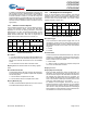
GPIO bit interrupts (Figure 21-4 and Figure 21-5) should be
disabled for any pins that are not being used for a wake-up
interrupt. This should be done even if the main GPIO Interrupt
Enable (Figure 21-1) is off.
Typical code for entering suspend is shown below:
... ; All GPIO set to low-power state (no floating
pins, and bit interrupts disabled unless
using for wake-up)
... ; Enable GPIO and/or wake-up timer
interrupts if desired for wake-up
... ; Select clock mode for wake-up (see
Section 11.1)
mov a, 09h ; Set suspend and run bits
iowr FFh ; Write to Status and Control Register –
Enter suspend, wait for GPIO/wake-up
interrupt or USB activity
nop ; This executes before any ISR
... ; Remaining code for exiting suspend
routine
11.1 Clocking Mode on Wake-up from Suspend
When exiting suspend on a wake-up event, the device can be
configured to run in either Internal or External Clock mode.
The mode is selected by the state of the External Oscillator
Enable bit in the Clock Configuration Register (Figure 9-2).
Using the Internal Clock saves the external oscillator start-up
time and keeps that oscillator off for additional power savings.
The external oscillator mode can be activated when desired,
similar to operation at power-up.
The sequence of events for these modes is as follows:
Wake in Internal Clock Mode:
1. Before entering suspend, clear bit 0 of the Clock Configu-
ration Register. This selects Internal clock mode after sus-
pend.
2. Enter suspend mode by setting the suspend bit of the
Processor Status and Control Register.
3. After a wake-up event, the internal clock starts immediately
(within 2 µs).
4. A time-out period of 8 µs passes, and then firmware
execution begins.
5. At some later point, to activate External Clock mode, set bit
0 of the Clock Configuration Register. This halts the internal
clocks while the external clock becomes stable. After an
additional time-out (128 µs or 4 ms, see Section 9.0),
firmware execution resumes.
Wake in External Clock Mode:
1. Before entering suspend, the external clock must be select-
ed by setting bit 0 of the Clock Configuration Register. Make
sure this bit is still set when suspend mode is entered. This
selects External clock mode after suspend.
2. Enter suspend mode by setting the suspend bit of the
Processor Status and Control Register.
3. After a wake-up event, the external oscillator is started. The
clock is monitored for stability (this takes approximately
50–100 µs with a ceramic resonator).
4. After an additional time-out period (128 µs or 4 ms, see
Section 9.0), firmware execution resumes.
11.2 Wake-up Timer
The wake-up timer runs whenever the wake-up interrupt is
enabled, and is turned off whenever that interrupt is disabled.
Operation is independent of whether the device is in suspend
mode or if the global interrupt bit is enabled. Only the Wake-up
Timer Interrupt Enable bit (Figure 21-1) controls the wake-up
timer.
Once this timer is activated, it will give interrupts after its
time-out period (see below). These interrupts continue period-
ically until the interrupt is disabled. Whenever the interrupt is
disabled, the wake-up timer is reset, so that a subsequent
enable always results in a full wake-up time.
The wake-up timer can be adjusted by the user through the
Wake-up Timer Adjust bits in the Clock Configuration Register
(Figure 9-2). These bits clear on reset. In addition to allowing
the user to select a range for the wake-up time, a firmware
algorithm can be used to tune out initial process and operating
condition variations in this wake-up time. This can be done by
timing the wake-up interrupt time with the accurate 1.024-ms
timer interrupt, and adjusting the Timer Adjust bits accordingly
to approximate the desired wake-up time.