
User`s guide


CY7C63722C
CY7C63723C
CY7C63743C
FOR
FOR
Document #: 38-08022 Rev. *C Page 8 of 49
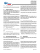
8.2 Data Memory Organization
The CY7C637xxC microcontrollers provide 256 bytes of data
RAM. In normal usage, the SRAM is partitioned into four
areas: program stack, data stack, user variables and USB
endpoint FIFOs as shown below.
8.3 I/O Register Summary
I/O registers are accessed via the I/O Read (IORD) and I/O
Write (IOWR, IOWX) instructions. IORD reads the selected
port into the accumulator. IOWR writes data from the accumu-
lator to the selected port. Indexed I/O Write (IOWX) adds the
contents of X to the address in the instruction to form the port
address and writes data from the accumulator to the specified
port. Note that specifying address 0 with IOWX (e.g., IOWX
0h) means the I/O port is selected solely by the contents of X.
Note: All bits of all registers are cleared to all zeros on
reset, except the Processor Status and Control Register
(Figure 20-1). All registers not listed are reserved, and should
never be written by firmware. All bits marked as reserved
should always be written as 0 and be treated as undefined by
reads.
After reset Address
8-bit DSP 8-bit PSP 0x00 Program Stack Growth
(User’s firmware moves DSP)
8-bit DSP User Selected Data Stack Growth
User Variables
0xE8
USB FIFO for Address A endpoint 2
0xF0
USB FIFO for Address A endpoint 1
0xF8
USB FIFO for Address A endpoint 0
Top of RAM Memory 0xFF
Figure 8-2. Data Memory Organization
Table 8-1. I/O Register Summary
Register Name I/O Address Read/Write Function Fig.
Port 0 Data 0x00 R/W GPIO Port 0 12-2
Port 1 Data 0x01 R/W GPIO Port 1 12-3
Port 2 Data 0x02 R Auxiliary input register for D+, D–, VREG, XTALIN 12-8
Port 0 Interrupt Enable 0x04 W Interrupt enable for pins in Port 0 21-4
Port 1 Interrupt Enable 0x05 W Interrupt enable for pins in Port 1 21-5
Port 0 Interrupt Polarity 0x06 W Interrupt polarity for pins in Port 0 21-6
Port 1 Interrupt Polarity 0x07 W Interrupt polarity for pins in Port 1 21-7
Port 0 Mode0 0x0A W Controls output configuration for Port 0 12-4
Port 0 Mode1 0x0B W 12-5
Port 1 Mode0 0x0C W Controls output configuration for Port 1 12-6
Port 1 Mode1 0x0D W 12-7