CY8C21634/CY8C21534 CY8C21434/CY8C21334/CY8C21234 PSoC® Programmable System-on-Chip Features ■ ■ Powerful Harvard Architecture Processor ❐ M8C Processor Speeds up to 24 MHz ❐ Low power at high speed ❐ 2.4V to 5.25V Operating Voltage ❐ Operating Voltages Down to 1.
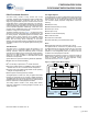
CY8C21634/CY8C21534 CY8C21434/CY8C21334/CY8C21234 PSoC Functional Overview The PSoC family consists of many devices with on-chip controllers. These devices are designed to replace multiple traditional MCU-based system components with one low cost single-chip programmable component. A PSoC device includes configurable blocks of analog and digital logic, and programmable interconnect.
CY8C21634/CY8C21534 CY8C21434/CY8C21334/CY8C21234 The Analog System The Analog Multiplexer System The Analog System consists of 4 configurable blocks that allow the creation of complex analog signal flows. Analog peripherals are very flexible and may be customized to support specific application requirements. Some of the common PSoC analog functions for this device (most available as user modules) are: The Analog Mux Bus can connect to every GPIO pin.
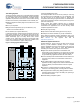
CY8C21634/CY8C21534 CY8C21434/CY8C21334/CY8C21234 PSoC Device Characteristics Depending on your PSoC device characteristics, the digital and analog systems can have 16, 8, or 4 digital blocks and 12, 6, or 4 analog blocks. Table 1 lists the resources available for specific PSoC device groups. The PSoC device covered by this data sheet is highlighted in this table.
CY8C21634/CY8C21534 CY8C21434/CY8C21334/CY8C21234 Development Tools PSoC Designer is a Microsoft® Windows-based, integrated development environment for the Programmable System-on-Chip (PSoC) devices. The PSoC Designer IDE runs on Windows XP or Windows Vista. This system provides design database management by project, an integrated debugger with In-Circuit Emulator, in-system programming support, and built-in support for third-party assemblers and C compilers.
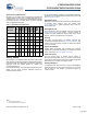
CY8C21634/CY8C21534 CY8C21434/CY8C21334/CY8C21234 Designing with PSoC Designer The development process for the PSoC device differs from that of a traditional fixed function microprocessor. The configurable analog and digital hardware blocks give the PSoC architecture a unique flexibility that pays dividends in managing specification change during development and by lowering inventory costs.
CY8C21634/CY8C21534 CY8C21434/CY8C21334/CY8C21234 Document Conventions Units of Measure Acronyms Used A units of measure table is located in the Electrical Specifications section. Table 2 on page 7 lists all the abbreviations used to measure the PSoC devices. The following table lists the acronyms that are used in this document. Table 2.
CY8C21634/CY8C21534 CY8C21434/CY8C21334/CY8C21234 Pin Information The CY8C21x34 PSoC device is available in a variety of packages which are listed in the following tables. Every port pin (labeled with a “P”) is capable of Digital I/O and connection to the common analog bus. However, Vss, Vdd, SMP, and XRES are not capable of Digital I/O. 16-Pin Part Pinout Figure 3.
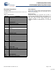
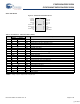
CY8C21634/CY8C21534 CY8C21434/CY8C21334/CY8C21234 20-Pin Part Pinout Figure 4. CY8C21334 20-Pin PSoC Device A, I, M, P0[7] A, I, M, P0[5] A, I, M, P0[3] A, I, M, P0[1] Vss M,I2C SCL,P1[7] M,I2C SDA, P1[5] M,P1[3] M,I2C SCL,P1[1] Vss 1 2 3 4 5 6 7 8 9 10 SSOP 20 19 18 17 16 15 14 13 12 11 Vdd P0[6], A, I, M P0[4], A, I, M P0[2], A, I, M P0[0], A, I, M XRES P1[6],M P1[4], EXTCLK,M P1[2],M P1[0],I2C SDA, M Table 4. Pin Definitions - CY8C21334 20-Pin (SSOP) Pin No.
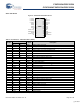
CY8C21634/CY8C21534 CY8C21434/CY8C21334/CY8C21234 28-Pin Part Pinout Figure 5. CY8C21534 28-Pin PSoC Device A, I, M, P0[7] A, I, M, P0[5] A, I, M, P0[3] A, I, M, P0[1] M,P2[7] M,P2[5] M, P2[3] M, P2[1] Vss M,I2C SCL,P1[7] M,I2C SDA, P1[5] M,P1[3] M,I2C SCL,P1[1] Vss 1 2 3 4 5 6 7 8 9 10 11 12 13 14 SSOP 28 27 26 25 24 23 22 21 20 19 18 17 16 15 Vdd P0[6], A, I, M P0[4], A, I, M P0[2], A, I, M P0[0], A, I, M P2[6],M P2[4],M P2[2],M P2[0],M XRES P1[6],M P1[4], EXTCLK,M P1[2],M P1[0],I2C SDA, M Table 5.
CY8C21634/CY8C21534 CY8C21434/CY8C21334/CY8C21234 32-Pin Part Pinout Figure 7. CY8C21634 32-Pin PSoC Device Figure 8. CY8C21434 32-Pin Sawn PSoC Device Sawn Figure 9. CY8C21634 32-Pin Sawn PSoC Device Sawn M, 12C SDA, P1[5] M, P1[3] M, 12C SCL, P1[1] Vss M, 12C SDA, P1[0] M, P1[2] M, EXTCLK, P1[4] M, P1[6] Document Number: 38-12025 Rev.
CY8C21634/CY8C21534 CY8C21434/CY8C21334/CY8C21234 Table 6. Pin Definitions - CY8C21434/CY8C21634 32-Pin (QFN)[4] Pin No.
CY8C21634/CY8C21534 CY8C21434/CY8C21334/CY8C21234 56-Pin Part Pinout The 56-pin SSOP part is for the CY8C21001 On-Chip Debug (OCD) PSoC device. Note This part is only used for in-circuit debugging. It is NOT available for production. Figure 10.
CY8C21634/CY8C21534 CY8C21434/CY8C21334/CY8C21234 Table 7. Pin Definitions - CY8C21001 56-Pin (SSOP) (continued) Pin No.
CY8C21634/CY8C21534 CY8C21434/CY8C21334/CY8C21234 Register Reference This chapter lists the registers of the CY8C21x34 PSoC device. For detailed register information, refer the PSoC Technical Reference Manual. Register Conventions The register conventions specific to this section are listed in Table 8. Table 8.
CY8C21634/CY8C21534 CY8C21434/CY8C21334/CY8C21234 Table 9.
CY8C21634/CY8C21534 CY8C21434/CY8C21334/CY8C21234 Table 10.
CY8C21634/CY8C21534 CY8C21434/CY8C21334/CY8C21234 Electrical Specifications This section presents the DC and AC electrical specifications of the CY8C21x34 PSoC device. For up to date electrical specifications, visit the web site http://www.cypress.com/psoc. Specifications are valid for -40oC ≤ TA ≤ 85oC and TJ ≤ 100oC as specified, except where noted. Refer Table 23 on page 27 for the electrical specifications on the IMO using SLIMO mode. Figure 11. Voltage versus CPU Frequency Figure 14.
CY8C21634/CY8C21534 CY8C21434/CY8C21334/CY8C21234 Absolute Maximum Ratings Symbol Description TSTG Storage Temperature Min -55 Typ 25 Max +100 Units oC TA Vdd VIO Ambient Temperature with Power Applied Supply Voltage on Vdd Relative to Vss DC Input Voltage – – – DC Voltage Applied to Tri-state IMIO ESD LU Maximum Current into any Port Pin Electro Static Discharge Voltage Latch-up Current – – – +85 +6.0 Vdd + 0.5 Vdd + 0.5 +50 – 200 oC VIOZ -40 -0.5 Vss 0.5 Vss 0.
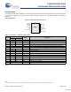
CY8C21634/CY8C21534 CY8C21434/CY8C21334/CY8C21234 DC Electrical Characteristics DC Chip-Level Specifications Table 12 lists the guaranteed maximum and minimum specifications for the voltage and temperature ranges: 4.75V to 5.25V and -40°C ≤ TA ≤ 85°C, 3.0V to 3.6V and -40°C ≤ TA ≤ 85°C, or 2.4V to 3.0V and -40°C ≤ TA ≤ 85°C, respectively. Typical parameters apply to 5V, 3.3V, or 2.7V at 25°C and are for design guidance only. Table 12.
CY8C21634/CY8C21534 CY8C21434/CY8C21334/CY8C21234 Table 13. 5V and 3.3V DC GPIO Specifications (continued) Symbol VIH VH IIL CIN Description Input High Level Input Hysteresis Input Leakage (Absolute Value) Capacitive Load on Pins as Input Min 2.1 – – – Typ – 60 1 3.5 Max COUT Capacitive Load on Pins as Output Units Notes V Vdd = 3.0 to 5.25. mV nA Gross tested to 1 μA. pF Package and pin dependent. Temp = 25oC. pF Package and pin dependent. Temp = 25oC. – 3.
CY8C21634/CY8C21534 CY8C21434/CY8C21334/CY8C21234 Table 16. 3.3V DC Operational Amplifier Specifications Symbol Min Typ Max Units – 2.5 15 mV TCVOSOA Average Input Offset Voltage Drift – 10 – μV/oC IEBOA Input Leakage Current (Port 0 Analog Pins) – 200 – pA Gross tested to 1 μA. IEBOA00 Input Leakage Current (Port 0, Pin 0 Analog pin) – 50 – nA Gross tested to 1 μA. CINOA Input Capacitance (Port 0 Analog Pins) – 4.5 9.5 pF Package and pin dependent. Temp = 25oC.
CY8C21634/CY8C21534 CY8C21434/CY8C21334/CY8C21234 DC Switch Mode Pump Specifications Table 19 lists the guaranteed maximum and minimum specifications for the voltage and temperature ranges: 4.75V to 5.25V and -40°C ≤ TA ≤ 85°C, 3.0V to 3.6V and -40°C ≤ TA ≤ 85°C, or 2.4V to 3.0V and -40°C ≤ TA ≤ 85°C, respectively. Typical parameters apply to 5V, 3.3V, or 2.7V at 25°C and are for design guidance only. Table 19.
CY8C21634/CY8C21534 CY8C21434/CY8C21334/CY8C21234 Figure 15. Basic Switch Mode Pump Circuit D1 Vdd V PUMP L1 V BAT + SMP Battery PSoC C1 Vss DC Analog Mux Bus Specifications Table 20 lists the guaranteed maximum and minimum specifications for the voltage and temperature ranges: 4.75V to 5.25V and -40°C ≤ TA ≤ 85°C, 3.0V to 3.6V and -40°C ≤ TA ≤ 85°C, or 2.4V to 3.0V and -40°C ≤ TA ≤ 85°C, respectively. Typical parameters apply to 5V, 3.3V, or 2.7V at 25°C and are for design guidance only.
CY8C21634/CY8C21534 CY8C21434/CY8C21334/CY8C21234 DC POR and LVD Specifications Table 21 lists the guaranteed maximum and minimum specifications for the voltage and temperature ranges: 4.75V to 5.25V and -40°C ≤ TA ≤ 85°C, 3.0V to 3.6V and -40°C ≤ TA ≤ 85°C, or 2.4V to 3.0V and -40°C ≤ TA ≤ 85°C, respectively. Typical parameters apply to 5V, 3.3V, or 2.7V at 25°C and are for design guidance only. Table 21. DC POR and LVD Specifications Symbol Description Min Typ Max Units Notes – 2.36 2.82 4.55 2.
CY8C21634/CY8C21534 CY8C21434/CY8C21334/CY8C21234 DC Programming Specifications Table 22 lists the guaranteed maximum and minimum specifications for the voltage and temperature ranges: 4.75V to 5.25V and -40°C ≤ TA ≤ 85°C, 3.0V to 3.6V and -40°C ≤ TA ≤ 85°C, or 2.4V to 3.0V and -40°C ≤ TA ≤ 85°C, respectively. Typical parameters apply to 5V, 3.3V, or 2.7V at 25°C and are for design guidance only. Table 22.
CY8C21634/CY8C21534 CY8C21434/CY8C21334/CY8C21234 AC Electrical Characteristics AC Chip-Level Specifications The following tables list the guaranteed maximum and minimum specifications for the voltage and temperature ranges: 4.75V to 5.25V and -40°C ≤ TA ≤ 85°C, 3.0V to 3.6V and -40°C ≤ TA ≤ 85°C, or 2.4V to 3.0V and -40°C ≤ TA ≤ 85°C, respectively. Typical parameters apply to 5V, 3.3V, or 2.7V at 25°C and are for design guidance only. Table 23. 5V and 3.
CY8C21634/CY8C21534 CY8C21434/CY8C21334/CY8C21234 Table 24. 2.7V AC Chip-Level Specifications Symbol FIMO12 Description Internal Main Oscillator Frequency for 12 MHz Min 11.5 Typ 120 Max 12.7[16,17,18] Units MHz FIMO6 Internal Main Oscillator Frequency for 6 MHz 5.5 6 6.5[16,17,18] MHz FCPU1 CPU Frequency (2.7V Nominal) 0.093 3 3.15[16,17] MHz FBLK27 Digital PSoC Block Frequency (2.7V Nominal) 0 12 12.
CY8C21634/CY8C21534 CY8C21434/CY8C21334/CY8C21234 Figure 17. 32 kHz Period Jitter (ILO) Timing Diagram Jitter32k F 32K1 Notes 16. 2.4V < Vdd < 3.0V. 17. Accuracy derived from Internal Main Oscillator with appropriate trim for Vdd range. 18. See Application Note AN2012 “Adjusting PSoC Microcontroller Trims for Dual Voltage-Range Operation” for information on maximum frequency for user modules. Document Number: 38-12025 Rev.
CY8C21634/CY8C21534 CY8C21434/CY8C21334/CY8C21234 AC General Purpose I/O Specifications The following tables list the guaranteed maximum and minimum specifications for the voltage and temperature ranges: 4.75V to 5.25V and -40°C ≤ TA ≤ 85°C, 3.0V to 3.6V and -40°C ≤ TA ≤ 85°C, or 2.4V to 3.0V and -40°C ≤ TA ≤ 85°C, respectively. Typical parameters apply to 5V, 3.3V, or 2.7V at 25°C and are for design guidance only. Table 25. 5V and 3.
CY8C21634/CY8C21534 CY8C21434/CY8C21334/CY8C21234 AC Analog Mux Bus Specifications Table 29 lists the guaranteed maximum and minimum specifications for the voltage and temperature ranges: 4.75V to 5.25V and -40°C ≤ TA ≤ 85°C, 3.0V to 3.6V and -40°C ≤ TA ≤ 85°C, or 2.4V to 3.0V and -40°C ≤ TA ≤ 85°C, respectively. Typical parameters apply to 5V, 3.3V, or 2.7V at 25°C and are for design guidance only. Table 29. AC Analog Mux Bus Specifications Symbol FSW Description Switch Rate Min – Typ – Max 3.
CY8C21634/CY8C21534 CY8C21434/CY8C21334/CY8C21234 Table 31. 2.7V AC Digital Block Specifications Function Description All Functions Maximum Block Clocking Frequency Timer Capture Pulse Width Maximum Frequency, With or Without Capture Counter Dead Band Enable Pulse Width Min Typ Max Units 12.7 MHz 100[20] – – ns – – 12.7 MHz 100 – – ns Maximum Frequency, No Enable Input – – 12.7 MHz Maximum Frequency, Enable Input – – 12.
CY8C21634/CY8C21534 CY8C21434/CY8C21334/CY8C21234 Table 33. 3.3V AC External Clock Specifications Symbol Description Min Typ Max Units Notes FOSCEXT Frequency with CPU Clock divide by 1 0.093 – 12.3 MHz Maximum CPU frequency is 12 MHz at 3.3V. With the CPU clock divider set to 1, the external clock must adhere to the maximum frequency and duty cycle requirements. FOSCEXT Frequency with CPU Clock divide by 2 or greater 0.186 – 24.
CY8C21634/CY8C21534 CY8C21434/CY8C21334/CY8C21234 AC Programming Specifications Table 35 lists the guaranteed maximum and minimum specifications for the voltage and temperature ranges: 4.75V to 5.25V and -40°C ≤ TA ≤ 85°C, or 3.0V to 3.6V and -40°C ≤ TA ≤ 85°C, respectively. Typical parameters apply to 5V, 3.3V, or 2.7V at 25°C and are for design guidance only. Table 35.
CY8C21634/CY8C21534 CY8C21434/CY8C21334/CY8C21234 Table 37. 2.7V AC Characteristics of the I2C SDA and SCL Pins (Fast Mode not Supported) Symbol Description FSCLI2C THDSTAI2C SCL Clock Frequency Hold Time (repeated) START Condition. After this period, the first clock pulse is generated.
CY8C21634/CY8C21534 CY8C21434/CY8C21334/CY8C21234 Packaging Information This section shows the packaging specifications for the CY8C21x34 PSoC device with the thermal impedances for each package. Important Note Emulation tools may require a larger area on the target PCB than the chip’s footprint. For a detailed description of the emulation tools’ dimensions, refer to the drawings located at http://www.cypress.com/design/MR10161. Figure 20. 16-Pin (150-Mil) SOIC 8 1 PIN 1 ID DIMENSIONS IN INCHES[MM] MIN.
CY8C21634/CY8C21534 CY8C21434/CY8C21334/CY8C21234 Figure 22. 28-Pin (210-Mil) SSOP 51-85079 *C Figure 23. 32-Pin (5x5 mm 0.60 MAX) QFN E-PAD X, Y for this product is 3.53 mm, 3.53 mm (+/-0.11 mm) 001-06392 *A Document Number: 38-12025 Rev.
CY8C21634/CY8C21534 CY8C21434/CY8C21334/CY8C21234 Figure 24. 32-Pin (5x5 mm) QFN X = 138 MIL Y = 138 MIL 51-85188 *C Figure 25. 32-Pin (5 X 5 X 0.4MM) QFN (SAWN 1.85 X 2.85) EPAD 001-44368 *A Document Number: 38-12025 Rev.
CY8C21634/CY8C21534 CY8C21434/CY8C21334/CY8C21234 Figure 26. 32-Pin Thin Sawn QFN Package 001-48913 *A Figure 0-1. 32-Pin Sawn QFN Package 001-30999 *B Important Note For information on the preferred dimensions for mounting QFN packages, see the following Application Note at http://www.amkor.com/products/notes_papers/MLFAppNote.pdf. Document Number: 38-12025 Rev.
CY8C21634/CY8C21534 CY8C21434/CY8C21334/CY8C21234 Figure 27. 56-Pin (300-Mil) SSOP 51-85062 *C Thermal Impedances Table 38. Thermal Impedances per Package Typical θJA [23] 123 oC/W 117 oC/W 96 oC/W 27 oC/W 22 oC/W Package 16 SOIC 20 SSOP 28 SSOP 32 QFN[24] 5x5 mm 0.60 MAX 32 QFN[24] 5x5 mm 0.93 MAX Typical θJC 55 oC/W 41 oC/W 39 oC/W 15 oC/W 12 oC/W Solder Reflow Peak Temperature Following is the minimum solder reflow peak temperature to achieve good solderability. Table 39.
CY8C21634/CY8C21534 CY8C21434/CY8C21334/CY8C21234 Development Tool Selection This section presents the development tools available for all current PSoC device families including the CY8C21x34 family. Software PSoC Designer™ At the core of the PSoC development software suite is PSoC Designer, used to generate PSoC firmware applications. PSoC Designer is available free of charge at http://www.cypress.com/psocdesigner and includes a free C compiler.
CY8C21634/CY8C21534 CY8C21434/CY8C21334/CY8C21234 Device Programmers CY3207ISSP In-System Serial Programmer (ISSP) All device programmers can be purchased from the Cypress Online Store. The CY3207ISSP is a production programmer. It includes protection circuitry and an industrial case that is more robust than the MiniProg in a production-programming environment. CY3216 Modular Programmer The CY3216 Modular Programmer kit features a modular programmer and the MiniProg1 programming unit.
CY8C21634/CY8C21534 CY8C21434/CY8C21334/CY8C21234 Temperature Range Digital I/O Pins Analog Inputsa Analog Outputs XRES Pin 8K 512 Yes -40°C to +85°C 4 4 12 12[28] 0 No 16 Pin (150-Mil) SOIC (Tape and Reel) CY8C21234-24SXIT 8K 512 Yes -40°C to +85°C 4 4 12 12[28] 0 No 20 Pin (210-Mil) SSOP CY8C21334-24PVXI 8K 512 No -40°C to +85°C 4 4 16 16[28] 0 Yes 20 Pin (210-Mil) SSOP (Tape and Reel) CY8C21334-24PVXIT 8K 512 No -40°C to +85°C 4 4 16 16[28] 0 Yes 28 Pin
CY8C21634/CY8C21534 CY8C21434/CY8C21334/CY8C21234 Ordering Code Definitions CY 8 C 21 xxx-24xx Package Type: Thermal Rating: PX = PDIP Pb-Free C = Commercial SX = SOIC Pb-Free I = Industrial PVX = SSOP Pb-Free E = Extended LFX/LKX = QFN Pb-Free AX = TQFP Pb-Free Speed: 24 MHz Part Number Family Code Technology Code: C = CMOS Marketing Code: 8 = Cypress PSoC Company ID: CY = Cypress Document Number: 38-12025 Rev.
CY8C21634/CY8C21534 CY8C21434/CY8C21334/CY8C21234 Document History Page Document Title: CY8C21234/CY8C21334/CY8C21434/CY8C21534/CY8C21634 PSoC® Programmable System-on-Chip Document Number: 38-12025 Orig. of Submission Revision ECN No. Description of Change Change Date ** 227340 HMT See ECN New silicon and document (Revision **). *A 235992 SFV See ECN Updated Overview and Electrical Spec. chapters, along with revisions to the 24-pin pinout part. Revised the register mapping tables. Added a SSOP 28-pin part.
CY8C21634/CY8C21534 CY8C21434/CY8C21334/CY8C21234 Document Title: CY8C21234/CY8C21334/CY8C21434/CY8C21534/CY8C21634 PSoC® Programmable System-on-Chip Document Number: 38-12025 *R 2762499 JVY 09/11/2009 Updated DC GPIO, AC Chip-Level, and AC Programming Specifications as follows: Modified FIMO6 and TWRITE specifications. Replaced TRAMP (time) specification with SRPOWER_UP (slew rate) specification. Added note [11] to Flash Endurance specification.