
Specifications


CY3214-PSoCEVALUSB Kit Guide, Doc No. 001-67030 Rev. *B 23
Hardware
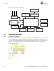
4.2.2 CapSense
®
Buttons (P3[0], P3[7]), and Sliders (Port5)
There are two CapSense buttons and eight element CapSense sliders on the CY3214-
PSoCEVALUSB kit. CapSense Sigma Delta uses an external modulation capacitor (CMOD), the
copper sensor pad on the CY3214 PSoCEVALUSB board, and bleed resistor (Rb) in addition to the
sensor capacitor (Cx).
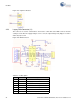
Bleed Resistor (Rb): The CSD uses the switched capacitor circuitry to convert the sensor
capacitance into a voltage, which is compared to a reference voltage. When the capacitor voltage
reaches the reference voltage, the comparator triggers a bleed resistor discharging the capacitor.
After the capacitor voltage discharges below the reference voltage, the bleed resistor is left floating
to allow the capacitor to continue charging. The comparator output becomes a bit-stream as it
toggles the bleed resistor and manipulates its input voltage. This bit stream is ANDed with a pulse
width modulator (PWM) to provide consistent stream framing. The number of counts in each frame is
analyzed to determine if the capacitive sensor is activated.
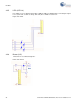
Modulation Capacitor (CMOD): The capacitor CMOD acts to attenuate high-frequency noise. The
pin assignment for CapSense buttons used in the CapSense code example (see My First Code
Example on page 31) are as follows:
B2 – P3[7]
B3 – P3[0]
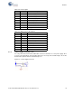
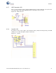
The slider segments pin assignment used in My First Code Example on page 31 are as follows:
Slider 0 – P5[7]
Slider 1 – P5[5]
Slider 2 – P5[3]
Slider 3 – P5[1]
Slider 4 – P5[0]
Slider 5 – P5[2]
Slider 6 – P5[4]
Slider 7 – P5[6]
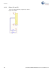
Figure 4-4. CapSense Sliders