
Specifications


CY3214-PSoCEVALUSB Kit Guide, Doc No. 001-67030 Rev. *B 25
Hardware
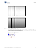
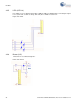
4.2.4 Power Supply Connector (J13)
You can power the board from the USB cable or from an external 9 V to 12 V power supply. D1 is
used as a protecting diode. The protecting diodes are necessary if the load discharges are slower
than the filter capacitor after the rectification process.
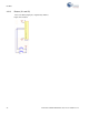
Figure 4-7. Power Supply Connector
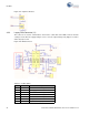
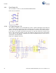
8 R2in Clear to send (IN)
9 R2out Clear to send (OUT)
10 T2in Request to send (IN)
11 T1in Transmitted data (IN)
12 R1out Receive data (OUT)
13 R1in Receive data (IN)
14 T1out Transmitted data (OUT)
15 Gnd Ground
16 Vcc Vcc supply
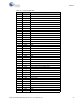
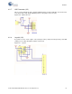
Table 4-3. DB9 Connector Description
Pin No Pin Name Description
1 DCD Carrier detect
2 RD Receive data
3 TD Transmit data
4 DTR Data terminal ready
5 SGND System ground
6 DSR Data set ready
7 RTS Request to send
8 CTS Clear to send
9 RI Ring indicator
Table 4-2. IC Description
Pin No. Pin Name Description