
User guide


CY8CKIT-002 MiniProg3 User Guide, Doc. # 001-59350 Rev. *E 17
Technical Description
3.1.5 Reference
For more information on the PSoC 3 and PSoC 5LP JTAG, SWD, and I
2
C interfaces, see the PSoC
3 and PSoC 5LP Technical Reference Manuals. For more information on PSoC 1 interfaces, see the
PSoC 1 Technical Reference Manual.
3.2 Connectors
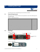
3.2.1 5-Pin Connector
The 5-pin connector is configured as a single row with 100-mil pitch. It is designed to mate with a
Molex model 22-23-2051 (straight) or 22-05-3051 (right angle) male header with a key tab.
Figure 3-2. 5-Pin Connector with Pin Assignments
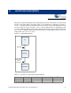
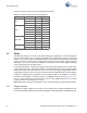
3.2.2 10-Pin Connector
The 10-pin connector is configured as a dual row with 50-mil pitch. It is used with a ribbon cable
(provided) to mate to a similar connector on the target board. The recommended mating connectors
are the Samtec FTSH-105-01-L-DV-K (surface mount) and the FTSH-105-01-L-D-K (through hole)
or similar connectors available from other vendors. The signal assignment is shown in Figure 3-3.
When programming JTAG devices, note that MiniProg3 does not support nTRST pins.
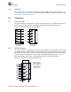
Figure 3-3. 10-Pin Connector with Pin Assignments
MiniProg3
(End View)
Mating
Connector
SDAT
SCLK
XRES
GND
VTARG
XRES
TDI
TDO
TCK
TMS
VTARG
GND
GND
GND
GND
TDI
TDO
TCK
TMS
VTARG
GND
Pin 1
Note The ribbon
cable connector
extends beyond the
body of the
connector. Be sure
to allow room.
GND
GND
GND