
User manual

CY8C29466, CY8C29566
CY8C29666, CY8C29866
Document Number: 38-12013 Rev. *M Page 29 of 47
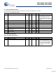
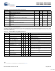
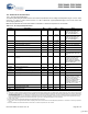
12.4 AC Electrical Characteristics
12.4.1 AC Chip-Level Specifications
The following table lists guaranteed maximum and minimum specifications for the voltage and temperature ranges: 4.75V to 5.25V
and -40°C ≤ T
A
≤ 85°C, or 3.0V to 3.6V and -40°C ≤ T
A
≤ 85°C, respectively. Typical parameters apply to 5V and 3.3V at 25°C and
are for design guidance only.
Note See the individual user module data sheets for information on maximum frequencies for user modules.
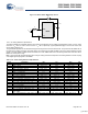
Table 12-17. AC Chip-Level Specifications
Symbol Description Min Typ Max Units Notes
F
IMO24
Internal Main Oscillator Frequency for 24 MHz 23.4 24 24.6
[9,10,11]
MHz Trimmed for 5V or 3.3V
operation using factory trim
values. See the figure on
page 19. SLIMO Mode = 0.
F
IMO6
Internal Main Oscillator Frequency for 6 MHz 5.5 6 6.5
[9,10,11]
MHz Trimmed for 5V or 3.3V
operation using factory trim
values. See the figure on
page 19. SLIMO Mode = 1.
F
CPU1
CPU Frequency (5V Nominal) 0.93 24 24.6
[9,10]
MHz
F
CPU2
CPU Frequency (3.3V Nominal) 0.93 12 12.3
[10,11]
MHz
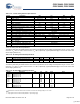
F
48M
Digital PSoC Block Frequency 0 48 49.2
[9,10, 12]
MHz Refer to the AC Digital Block
Specifications below.
F
24M
Digital PSoC Block Frequency 0 24 24.6
[10, 12]
MHz
F
32K1
Internal Low Speed Oscillator Frequency 15 32 64 kHz
F
32K2
External Crystal Oscillator – 32.768 – kHz Accuracy is capacitor and
crystal dependent. 50% duty
cycle
F
32K_U
Internal Low Speed Oscillator (ILO) Untrimmed
Frequency
5 – – kHz After a reset and before the m8c
starts to run, the ILO is not
trimmed. See the System
Resets section of the PSoC
Technical Reference Manual for
details on timing this
F
PLL
PLL Frequency – 23.986 – MHz A multiple (x732) of crystal
frequency.
Jitter24M2 24 MHz Period Jitter (PLL) – – 600 ps
T
PLLSLEW
PLL Lock Time 0.5 – 10 ms
T
PLLSLEWLOW
PLL Lock Time for Low Gain Setting 0.5 – 50 ms
T
OS
External Crystal Oscillator Startup to 1% – 250 500 ms
T
OSACC
External Crystal Oscillator Startup to 100 ppm – 300 600 ms The crystal oscillator frequency
is within 100 ppm of its final
value by the end of the T
osacc
period. Correct operation
assumes a properly loaded 1
uW maximum drive level
32.768 kHz crystal. 3.0V
≤ Vdd
≤ 5.5V, -40°C ≤ T
A
≤ 85°C.
Jitter32k 32 kHz Period Jitter – 100 – ns
T
XRST
External Reset Pulse Width 10 – – μs
DC24M 24 MHz Duty Cycle 40 50 60 %
Notes
7. The 50,000 cycle flash endurance per block will only be guaranteed if the flash is operating within one voltage range. Voltage ranges are 3.0V to 3.6V and 4.75V to 5.25V.
8. A maximum of 36 x 50,000 block endurance cycles is allowed. This may be balanced between operations on 36x1 blocks of 50,000 maximum cycles each, 36x2 blocks
of 25,000 maximum cycles each, or 36x4 blocks of 12,500 maximum cycles each (to limit the total number of cycles to 36x50,000 and that no single block ever sees
more than 50,000 cycles).
For the full industrial range, the user must employ a temperature sensor user module (FlashTemp) and feed the result to the temperature argument before writing.
Refer to the Flash APIs Application Note AN2015 at http://www.cypress.com under Application Notes for more information.
9. 4.75V < Vdd < 5.25V.
10. Accuracy derived from Internal Main Oscillator with appropriate trim for Vdd range.
11. 3.0V < Vdd < 3.6V. See Application Note AN2012 “Adjusting PSoC Microcontroller Trims for Dual Voltage-Range Operation” for information on trimming for operation
at 3.3V.
12. See the individual user module data sheets for information on maximum frequencies for user modules
[+] Feedback